You're completely correct. In post #8 I realized that you were right when I took a closer look and compared both schematics (this one and the original Dean Hammonds schematic).

 THIS USER WAS CLUEBYFOURED
You're completely correct. In post #8 I realized that you were right when I took a closer look and compared both schematics (this one and the original Dean Hammonds schematic).
Senior Member
I like the Idea. How i use the Chip?Originally Posted by dave

On the Vsup/Swing Graph its linear, so when i supply it with ±5V it will output 10V p-p?
And the Offset, can it be set in the IC or have to be buffered/nulled externally?
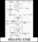
About the wrong OPA use Thing:
This is the original Design by Nicolay (weartronics) i hope i may reupload it here:
THIS USER WAS CLUEBYFOURED
weartronics is at least 10X more knowledgeable about electronics than I am.. if that's what he says, that's what I'd do. That's all I'll say. Perhaps he'll see this thread and give us his $.02.
Senior Member
Yes i hope this too. I should ask him about the Buffer thing... im not sure if it will still work when i change the Supply to ±12 V instead of the ±5V in his plans
i played with Multisim and the DRV134 a bit, but i think im going it wrong. Clipping here and there...
Senior Member
I had a second look and the amplifier WILL work, if you treat it as a non-inverting type (with Voffset acting as ground). That's great if you need a fixed amount of gain, but an inverting amplfier is a little easier to build and allows for some more flexibility when adjusting your gain. Both work, whatever floats your boat, I guess.
Senior Member
I would like an adjustable gain (with fixed offset). Just tell me how to do it Symmetrical
Senior Member
Well...
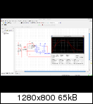
Im simulating weartronic's Circuti now, but it works "50%" only
The Vref Spurce gives stable 2.25 like it should.
And the first OpAmp really amplifies
But the second one gives not a symmetrical negative signal, instead just an negative offest to the + one!
any clue?
 Creaky Old Award Winning Bastard Technologist
The second opamp in the sim screen capture is NOT powered, see the Xs on the power leads? Sometimes the folks who create chip models do not always carry the power signals to where they should be, and this can cause a mess in the simulation code, because it does not have a proper bias on the device.
correct that and run it again and show us the waveforms.
Steve
Qui habet Christos, habet Vitam!
I should have rented the space under my name for advertising.
When I still could have...
Creaky Old Award Winning Bastard TechnologistThe second opamp in the sim is NOT powered, see the Xs on the power leads? Sometimes the folks who create chip models do not always carry the power signals to where they should be, and this can cause a mess in the simulation code, because it does not have a proper bias on the device.
correct that and run it again and show us the waveforms. Without the power its gonna act as a mess of diodes, and perhaps clip like your drawing shows..
Also you don't need R6-100 ohms in series with the 47K.
Steve
Qui habet Christos, habet Vitam!
I should have rented the space under my name for advertising.
When I still could have...
Senior Member
OK i put a new TL072 at the other ones place and rewired the connections bevore/after R6 correctly
but its still not what i need...

 Posting Permissions

 Reply With Quote

