For those of us who are electronic theory challenged, is there a way to make this simple? I know there should be a resistor(s) with the 445 diodes somewhere between the driver and the diode.....but where and how?
I looked online at some led resistor calculators since that is all there is. Assuming that a diode is a diode (led or laser diode), I was trying to see what resistors work and where to put them. For either a single diode or a 4 diode setup. For the single diode a calculator came up with this:

For the 4 diodes another site gave me a schematic to wire the diodes in parallel and looked like this:

That site when I choose only 1 diode still put the resistor on the - side.
One site tells me that using 1 diode the resistor goes in the + to diode and a different site tells me that for 4 diodes the resistor goes in the - sides???
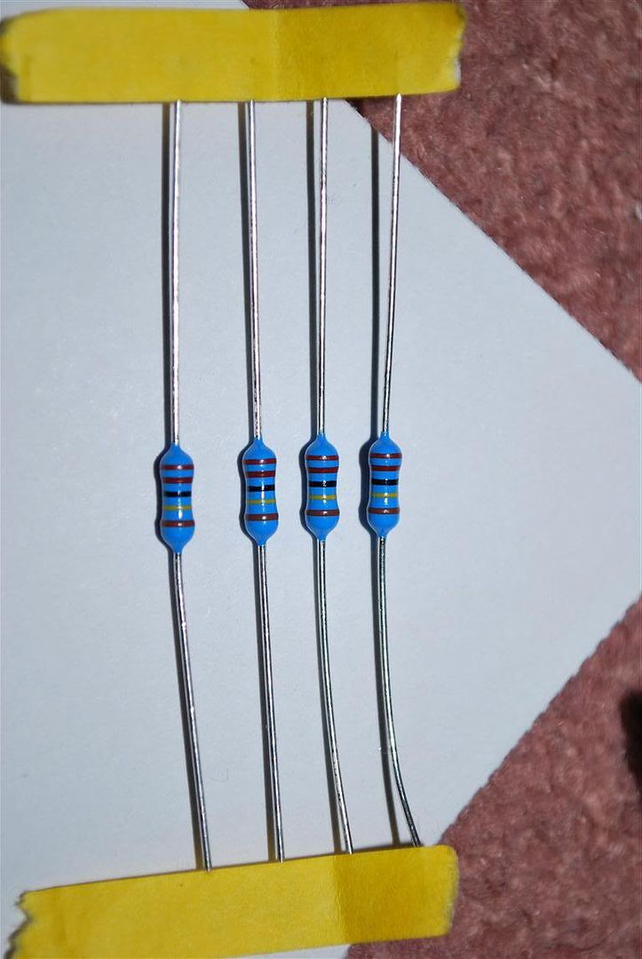
I was also told that for multiple diodes in series to put the resistor across the + and - for each diode... That does not seem right to me, but the person that told me to do that is VERY good with electronics.
OK, I'm confused as hell...! I am thinking the best way to do a 4 diode setup is in series, but where and how do I put resistors in?


 Reply With Quote

 )
)