Page 2 of 8 FirstFirst 123456 ... LastLast
Results 11 to 20 of 71

Thread: Help - Actually Hate the P3 Driver...

  1. #11
    Join Date
    Oct 2006
    Location
    Cleveland, Ohio
    Posts
    2,342

    Default

    Quote Originally Posted by LaNeK779 View Post
    is the cap necessary for all diodes wired in series andrew, or just the blue ones?
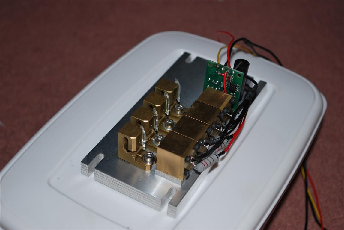
    I'd suggest adding it for all diode types, just to be sure. It's not necessary in all installations but some users have reported capacitive coupling between the first diode in the set and the casing which can give it spikes because it's riding at a high voltage relative to ground and the other diodes.

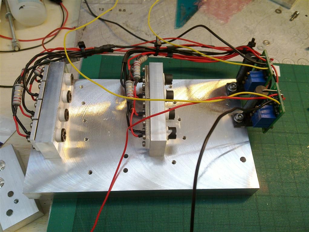
    I'm planning a 'break out board' for the new driver to be used with series setups that will simplify all of this.

  2. #12
    Join Date
    Apr 2008
    Location
    Poland
    Posts
    322

    Default

    I see You're not isolating the driver's transistor from baseplate ...
    Piotr.K

  3. #13
    Join Date
    Jun 2010
    Location
    Australia
    Posts
    3,734

    Default

    Quote Originally Posted by LesioQ View Post
    I see You're not isolating the driver's transistor from baseplate ...
    Piotr.K
    No need, it's an isolated plastic package.
    This space for rent.

  4. #14
    Join Date
    Dec 2006
    Location
    Essex, UK
    Posts
    8,648

    Default

    ok more issues...

    probably my fault but im blaming the driver

    now i know this setup works as ive done it before


    now ive got a same setup, 4 diodes wires in parallel with correct resistor. input voltage is 9v but i can only seem to get 250mw out of the diodes, the driver wont give anymore power.


    help....


    Eat Sleep Lase Repeat

  5. #15
    Join Date
    Jun 2010
    Location
    Zweibrücken, Germany
    Posts
    605

    Default

    Quote Originally Posted by andy_con View Post
    ok more issues...

    probably my fault but im blaming the driver

    now i know this setup works as ive done it before
    Are those 2.2 Ohm balancing resistors you got in there? If yes I believe that's too big for a 9V supply. Can your supply deliver at least 5A continuous? If yes then maybe you should try a 12V supply or smaller resistors around 1 Ohm.


    Cheers!

  6. #16
    Join Date
    Feb 2011
    Location
    Knutsford, UK
    Posts
    286

    Default

    Andy, I've had a good look at the pics and got an idea - are they both doing it or just one?

    Quote Originally Posted by andy_con View Post
    ok more issues...

    probably my fault but im blaming the driver

    now i know this setup works as ive done it before


    now ive got a same setup, 4 diodes wires in parallel with correct resistor. input voltage is 9v but i can only seem to get 250mw out of the diodes, the driver wont give anymore power.


    help....


  7. #17
    Join Date
    Dec 2006
    Location
    Essex, UK
    Posts
    8,648

    Default

    both sets doing it
    Eat Sleep Lase Repeat

  8. #18
    Join Date
    Feb 2011
    Location
    St. Louis
    Posts
    526

    Default

    Have you tested to see what the voltage is being supplied to the Modulation input(M+)? Just thinking.

  9. #19
    Join Date
    Dec 2006
    Location
    Essex, UK
    Posts
    8,648

    Default

    tried two different 5v psu, so know thats correct
    Eat Sleep Lase Repeat

  10. #20
    Join Date
    Feb 2011
    Location
    St. Louis
    Posts
    526

    Default

    I was going to suggest you use something to bridge the V+ and M+ temporarily to be sure since you are now only running 9V. But you said that you are sure.

Posting Permissions

  • You may not post new threads
  • You may not post replies
  • You may not post attachments
  • You may not edit your posts
  •