Results 1 to 10 of 10

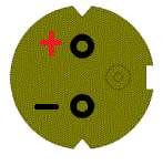
Thread: Laser Diode pin out, as viewed from the back to make life simple for all.

  1. #1
    Join Date
    May 2007
    Location
    Romania
    Posts
    1,041

    Default Laser Diode pin out, as viewed from the back to make life simple for all.

    So each time I need to test a diode, I keep having to look all over for its datasheet and as these are often a little confusing so I though to start this thread. If we all populate it, it will help everyone else too.

    It would be good to add a consistent title like : "445 9mm pin out and connection" so I am going to start with exactly that.

    Please keep to the format as in the title and red + and black - on your photos.

    Andy

    P.S. Decided to add a template to make this uniform and easy to update. Just download the template, add the connections and re-upload it with the model name.

    Attachment 31980
    Last edited by andyf97; 05-06-2012 at 09:36.

  2. #2
    Join Date
    May 2007
    Location
    Romania
    Posts
    1,041

    Default

    NDB7875 ( Apparently as used in some new video projectors )
    1.6W 445nm ( Tested to deliver 2.5W )

    If 1.7A ( Rated Max Current )
    Beam Divergence 14 X 44
    Ith 80mA - 220mA (Threshold )
    Vop 3.7V - 5.5V ( Operating Voltage )
    Emitter width 15um x 1um
    Capped version

    Notes this diode only has two pins

    Attachment 31983
    --------------------------------------------------------------------------------------------------------------

    Osram PLTB450 ( 5.6mm )
    1.6W 440nm - 460nm

    If 1.6A ( Rated Max Current )
    Beam Divergence 15 x 25
    Ith 200mA - 300mA (Threshold )
    Vop 6V ( Operating Voltage )
    Emitter width:15um x <1um
    Capped version

    Notes

    Attachment 31983
    --------------------------------------------------------------------------------------------------------------

    ML501P73
    500mW 638nm ( Tested to deliver 1.1W )

    If 800mA ( Rated Max Current )
    Beam Divergence 7.5 X 35
    Ith 90mA - 210mA (Threshold )
    Vop 1.9V - 2.6V ( Operating Voltage )
    Emitter width 100um ( Apparently )
    Open Can

    Notes, this diode has 4 notches but this does not mater if you keep your relationship to the pins only.

    Attachment 31983
    --------------------------------------------------------------------------------------------------------------

    ML520G71
    300mW 638nm ( Tested to deliver 750mW )

    If 400mA ( Rated Max Current )
    Beam Divergence 7 X 35
    Ith 80mA - 180mA (Threshold )
    Vop 1.9V - 2.6V ( Operating Voltage )
    Emitter width 60um ( Apparently )
    Capped version

    Notes

    Attachment 31983
    --------------------------------------------------------------------------------------------------------------
    Last edited by andyf97; 05-21-2012 at 03:38. Reason: update

  3. #3
    Join Date
    Jul 2007
    Location
    Knoxville, TN, USA
    Posts
    3,154

    Default

    GREAT idea - thanks for posting this!!
    RR

    Metrologic HeNe 3.3mw Modulated laser, 2 Radio Shack motors, and a broken mirror.
    1979.
    Sweet.....

  4. #4
    Join Date
    Feb 2011
    Location
    St. Louis
    Posts
    526

    Default

    Maybe it would work best to list several different configurations and the diodes that go with them. Like this. You could just copy them back to the OP when verified to be correct.

    Also if someone could fact check me on the Opnext diodes. I took this off the data sheet but I don't remember the 250mW being Case/LD negative and the 170mW is listed as case neutral.


    Case neutral

    M140/A140/H1600 445nm
    PL450/PL450B 450nm
    ML520G71 300mW 635nm
    ML501P73 500mW 635nm
    ML520G54 110mW 635nm
    HL63133DG 170mW 635nm
    12X S06J 405nm
    8X BDR-S03 405nm
    8X BDR-203 405nm
    6X GGW-H20L 405nm
    4X SF-AW210 405nm
    PHR-803T 405nm


    Case/LD Negative

    HL6388MG 250mW 635nm
    HL6385DG 150mW 635
    Sanyo 20mW 635nm
    Sanyo 40mW 635nm
    BDR-203 660nm
    BDR-205 660nm
    ML101J27 660nm
    LPC-815(LOC) 660nm
    Last edited by DTR; 05-06-2012 at 12:10.

  5. #5
    Join Date
    May 2007
    Location
    Romania
    Posts
    1,041

    Default

    Yep DTR, I was thinking the same too, but it takes someone to validate them. I am validating them as I test then uploading the data to be as 100% as possible with power and specs.

  6. #6
    Join Date
    Dec 2006
    Location
    denver,co
    Posts
    1,078

    Default

    Hey guys, when you get this finalized I Will Add this to the wiki. Or you guys can do it.. Feel free to add stuff..

    http://www.photonlexicon.com/wiki/in...n_Laser_Diodes

    chad


    When the going gets weird, the weird turn pro.


  7. #7
    Join Date
    May 2007
    Location
    Romania
    Posts
    1,041

    Default

    Hey chad, I was thinking the same, but better to wait until its more populated and correct, then you can take the data over. Just need to get more people contributing to the real data so feel free to promote also this thread.

  8. #8
    Join Date
    May 2007
    Location
    Romania
    Posts
    1,041

  9. #9
    Join Date
    Feb 2010
    Location
    Melbourne, Australia
    Posts
    1,106

    Default

    You should probably explain that the minus (negative) sign in red means the positive terminal (anode). It's visually confusing and should probably be changed to a plus sign.

  10. #10
    Join Date
    May 2007
    Location
    Romania
    Posts
    1,041

    Default

    Quote Originally Posted by taggalucci View Post
    You should probably explain that the minus (negative) sign in red means the positive terminal (anode). It's visually confusing and should probably be changed to a plus sign.
    good point, i will change it.

Posting Permissions

  • You may not post new threads
  • You may not post replies
  • You may not post attachments
  • You may not edit your posts
  •