lol ill see what time I get over xmas, the mounts consist of 3 different parts which need machining which is time consuming in its self and one of them is very complex and requires 3d milling

 Senior Member
lol ill see what time I get over xmas, the mounts consist of 3 different parts which need machining which is time consuming in its self and one of them is very complex and requires 3d milling
Eat Sleep Lase Repeat
Senior Member
I went ahead and started the new thread. Let me know what you think.
Senior Member
im just consulting with someone before I post a reply mate
Eat Sleep Lase Repeat
That's always been my feeling as well although, I suppose that's a very good point. We DON'T hear about a lot of failures from modestly overdriving diodes and, it's probbaly very true that 2-3-4 years from now, this could all be obsolete. 10 watt diodes with .5mrad for $8 using a $2 lens could be rolling out of China in 2018 or something. Look back at 4 years. Who knew??Originally Posted by andy_con

In the interim, this will be an interesting thread to follow.
Senior Member
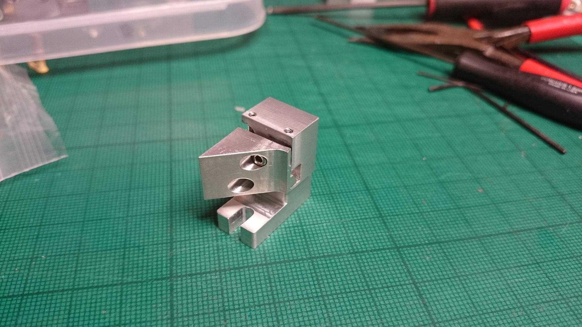
Found some time over the past few days to do a first prototype of the top adjustable mirror mounts.
Need to go back to the drawing board to do some alterations but I think it's actually going to work. The first prototype does work to a certain degree.
Eat Sleep Lase Repeat
Senior Member
Andy,
Nice work! If you are willing to share more images I would enjoy seeing them. If the cap head screws that are visible are providing the back force against the screws or balls, could you bore these holes from the back and not penetrate the angled front face? If they interact with springs you could choose to retain the springs with small pins that are inserted through right angle holes in the sides of the components. Also, if you can mill the base slot from the bottom, you can also place a shallow, say 0.25mm deep, channel along the center line of the base surface. This will significantly improve the mount's resistance to rotating about its base when adjusting it.
Senior Member
no more photos at the moment sorry.
no, cant relocate the screws in the angled head sorry. but it doesn't matter they are flush so wont affect a mirror.
not sure what you mean on 0.25mm channel?
Eat Sleep Lase Repeat
Senior Member
If you turn over the mount and look at the bottom, except for the notch, the surface appears flat. If you mill the notch with say a 6mm diameter mill, when you are done then replace the 6mm mill with a mill that is approximately between 6mm and the width of the mount. If the mount was 18 mm wide then the mill you use is 12mm in diameter, etc. Set the mill to cut a very shallow depression in line with the notch, center it as the notch is centered and when you are done you will leave two strips of material on each side of this central groove that actually contact the surface that the mount will be resting on. This is much more resistant to slipping when you adjust the mount than the "seemingly" flat base. Nothing is PERFECTLY flat.
Senior Member
oh right yeah, this gets done as standard and has done for a while now
but 0.25mm... I go for 0.1mm
Eat Sleep Lase Repeat
Senior Member
Of course. Dave @ LSP does not do this. It's a good idea, but not obvious to the market.but 0.25mm... I go for 0.1mm

 Posting Permissions

 Reply With Quote
 Bradfo69