Page 11 of 17 FirstFirst ... 789101112131415 ... LastLast
Results 101 to 110 of 165

Thread: How to create super bright laser beams

  1. #101
    Join Date
    Dec 2008
    Location
    veenwouden
    Posts
    2,580

    Default

    in comparison with the very smart minds working on this issue...I am a " Very Small Dog" indeed.....but I thought I would throw in a tidbit...

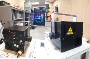
    In response to the comment by LS==>" I had thought it may be possible in theory to use a long glass parallelogram to accomplish the combining. The difference would be the entering beams would be exactly parallel and "stacked" next to each other when entering the glass. ".....Please see the attached pic of the internals of a " LaserKing " projector...OK....if you are done laughing....you must admit they have tried a novel beam combining approach approach !! I have no details as to what the beam propagations are....except that a long glass parallelogram is employed to combine both red and blue diodes.
    Laserking uses a beamsplitter plate instead of a PBS to combine 2 lasers of the same color.Here,s a link of CNI how it exactly works:

    http://www.cnilaser.com/Polarization...er%20plate.htm


    and a small picture......
    Attached Thumbnails Attached Thumbnails polarization splitter system.jpg  


    Interested in 6-12W RGB projectors with low divergence? Contact me by PM!

  2. #102
    Join Date
    Feb 2011
    Location
    New Hampshire
    Posts
    3,513

    Default

    I was so sure that this would work that I ordered two, 60 degree high dispersion prisms a couple of days ago and I have two precision rotation stages to adjust them with. The angle that these will need to be used at, to produce enough dispersion to make the spacing on the order of 10-20cm, is only a couple of degrees before total internal reflection occurs. The site that I linked to above demonstrates that this is practical. Also, I am going to allow for a 1/2 wave plate to make sure the polarization is optimized for minimum reflectance. At these angles the "bad" polarization will be seeing something like 10% reflectance/surface.

    "Your plan worked, Muad'Dib" The highest compliment you can receive. Thanks.

  3. #103
    Join Date
    Jun 2007
    Location
    Monroe, Mi USA
    Posts
    818

    Default

    Infamous lines from" Real Genius" !!!!!!!

    "Chris Knight: As you know, Mitch and I were working on the cyanide system. Well, earlier today it ate itself. But, these little set-backs are just what we need to take a giant step forward. Right, Kent? Needless to say, I was a little despondent about the melt down, but then, in the midst of my preparations for hari kiri, it came to me. It is possible to synthesize excited bromide in an argon matrix. Yes, it's an excimer frozen in its excited state.
    Bodie: Th... That's impossible.
    Chris Knight: It's a chemical laser but in solid, not gaseous, form. Put simply, in deference to you, Kent, it's like lasing a stick of dynamite. As soon as we apply a field, we couple to a state, it is radiatively coupled to the ground state. I figure we can extract at least ten to the twenty-first photons per cubic centimeter which will give one kilojoule per cubic centimeter at 600 nanometers, or, one megajoule per liter."

    SOOooooo...Perhaps you guys are on to something !!! Glad I had a very small part !! I remember seeing that beam combining layout and saved the pic. Like I have said B4...Our "Mind Lab" stretches around the world....and one can never tell where a novel, simple, inspired approach will actually move our hobby/passion forward !!!!

    We do not have million dollar labs.....huge budgets......( Some of us may have been considered for " White Coats" haha)...but then....we are not anchored down with convention. Most scientific advances at the turn of last century were fueled with passion and inspiration.....(OK....and good'ole capitalism !! ) There is no reason to completely discount our vector as a possible path to progress. That would be arrogant. Lite'em up !!

    CDBEAM=======>
    Beam Axiom #1 ~The Quantum well is DEEP ! Photons for ALL !!
    .
    Beam Axiom #2 ~Yes...As a matter of fact...I DO wear tinfoil on my head !!
    .
    Beam Axiom #3 ~Whe'n dout...Po ah Donk awn et !!
    .
    Beam Axiom #4 ~A Chicken in every Pot, and a Laser Lumia in every Livingroom !!
    .
    Beam Axiom #5 ~"Abstract Photonic Expressionism"....is "Abstractonimical" !!
    .
    Beam Axiom #6 ~ "A Posse ad Essea" ~ From being possible to being actual ...is the beam target !

  4. #104
    swamidog's Avatar
    swamidog is online now Jr. Woodchuckington Janitor III, Esq.
    Join Date
    Nov 2006
    Location
    santa fe, nm
    Posts
    1,545,761

    Default

    hmm.. maybe an amici prism...
    suppose you're thinkin' about a plate o' shrimp. Suddenly someone'll say, like, plate, or shrimp, or plate o' shrimp out of the blue, no explanation. No point in lookin' for one, either. It's all part of a cosmic unconciousness.

  5. #105
    Join Date
    Feb 2011
    Location
    New Hampshire
    Posts
    3,513

    Default

    I think an Amici prism (multiple prism) is in the right neighborhood, but the typical dispersion will be limited by the near contact spacing and it is this spacing that gives the resolving power, which is the inverse of the converging power. The narrow spectral range that we are discussing is on the order of 10-20nm. This is more in the range of what diffraction gratings or grisms deal with. However, their losses with the higher orders is what we are trying to avoid. The elegance with this approach is that typical, off the shelf prisms can be adjusted in spacing to meet the spectral range of interest.

  6. #106
    Join Date
    Aug 2008
    Location
    Seattle
    Posts
    220

    Default

    This patent illustration seems relevant:

    Click image for larger version. 

Name:	US08599487-20131203-D00002.png 
Views:	59 
Size:	26.1 KB 
ID:	45856

    http://www.google.com/patents/US8599487

  7. #107
    Join Date
    Feb 2011
    Location
    New Hampshire
    Posts
    3,513

    Default

    I'll bet there are a lot of patents for this general idea. This is not to diminish your search, but to put this technique in perspective. Telecommunications companies have been using this technique for years and I believe they originated the term, WDM. I'll bet Dilas, IPGPhotonics and others have incorporated this in their direct fiber-pigtailed lasers. I don't know if there are any non-infrared applications, however. Also, if this works then this complements the use of PBS to significantly increase the potential brightness and is accessible to low budget experimenters without the need to pay for pricy wavelength tailored lasers. Funny thing is, if there are a lot of fiercely defended patents out there then the only ones of us that might be able to utilize this are the non-commercial builders.

    At this moment, I am running an experiment with the stainless bar mounted on a two stage TEC and "grounded" at the opposite end to a thermally conductive spacer. The apparatus is within a hermetically sealed enclosure and the TEC is running at 5.5A and giving a 22C temperature differential over a 7.5cm gap. This is not so good. I calculated the bar to have a thermal conductivity that should have allowed a 60 degree differential at 7A. The base has a larger gradient than I thought it would. It's thick aluminum, but the thermistors (and I can feel it as well) show the gradient from under the TEC to under the "grounding" spacer is 7 degrees. In addition, there is no doubt that I used too thick a stainless bar, but thankfully I did choose stainless steel, brass would have been a total fail! I will mill/drill some material from the gaps between the future mounting points for the diodes and re-run the test tomorrow.

  8. #108
    Join Date
    Feb 2011
    Location
    New Hampshire
    Posts
    3,513

    Default

    I've uncovered the difficulty with the temperature differential. The stainless bar was probably too thick and so the removal of some thickness down to the next typical stock thickness helped, but the real bottle neck was in the region of the base plate near the hot side of the TEC. This area was surprisingly hot when I probed the thin border within 1cm of the TEC. I am wondering about the thermal conductivity of the 6061 Aluminum that I have been using for some time as the raw material for many of my components. It can not just be a thin oxide layer because this would act to keep heat both form entering as well as leaving. Nevertheless, placing a small heat exchanger right below the TEC has made a big difference. I now see a real world (not on paper), 44 degree C differential from one end of the bar to the other ( -22C,+22C). It took approximately 4 min. to get there without the diode mounts attached. The question will now be, how many degrees/diode will be required to generate clearly distinct wavelengths. This will determine how many diodes can be mounted along such a bar ( gaps+1).

  9. #109
    mixedgas's Avatar
    mixedgas is offline Creaky Old Award Winning Bastard Technologist
    Infinitus Excellentia Ion Laser Dominatus
    Join Date
    May 2007
    Location
    A lab with some dripping water on the floor.
    Posts
    9,905

    Default

    Planters, This raises the issue of cold starts when doing a show. What happens if a stagehand yanks your power at 30 seconds to the stage manager calling "Lasers, Cue 1 ,Go Cue!" ?

    Are we going back to lasers with an annoying warm up time? While I've dealt with that for years, it is one thing that I have been happy to reduce with the DPSS and Diode revolution. I still allow the DPSS lasers to warm up, by scanning prior to the show. Which is my projector keeps it's GM20 shutter.

    As much as I'd like to think everything is perfect at least 20 minutes to curtain, in reality things like rain, power dropouts, resetting the hoists, loading lighting desk files, and human nature cause pandemonium some times.

    Just something more to think about as you develop this technology.

    On the other hand I could use 4 watts of direct red without huge numbers of optics mounts, so I am optimistic.

    Steve
    Last edited by mixedgas; 01-01-2015 at 15:37.
    Qui habet Christos, habet Vitam!
    I should have rented the space under my name for advertising.
    When I still could have...

  10. #110
    Join Date
    Feb 2011
    Location
    New Hampshire
    Posts
    3,513

    Default

    Steve,

    The method I am using to set up these tests, I am pretty convinced will not be the method I will want to implement in a serious laser module. I have wrestled with (and won) the thermal bar technique because it seamed simpler and did not rely on the development of a multichannel TEC driver that has yet to be developed. One other advantage, that the bar had promised, was that the diodes were thermally coupled with a mechanical offset. This would keep them operating as a unit even if there was some variation in ambient temperatures. But, the advantages of a series of closed loops with a TEC dedicated to each diode has become more clear to me now that I've gone down this road some way.

    The coldest diode needs to be really cold to allow more diodes in the string and a three stage TEC is certainly the way to go here, but the thermal pumping capacity of three stage TEC's is pretty small and coupling to just the diode load as opposed to drawing down a string of diodes on a "leaky bridge" will undoubtedly allow lower temperatures. Three stage and even two stage TEC's are more expensive, but only the coldest diodes will need to achieve high thermal differentials, so as I envision it, the string might consist of say, one three stage, one two stage, another two stage, a single stage and finally a single stage that operates to actually heat the last diode. The operating temp will now be limited by the thermal pumping of the coldest diode, but the models I looked at from Ferrotec will drop the cold diode at better than 3 degrees/ sec, initially. This is another good reason to eliminate the massive metal bar. Also, by setting each diode to a specific temperature and holding it there, then manufacturing variability and occasional replacement of diodes will not produce the variable wavelength step that will undoubtedly occur with the bar.

    The other promise beside eliminating the number of downstream optics it that these beams will be much brighter, not only because they will be several times more intense as in watts/mm^2, but also because of the large gains in efficiency and visibility that occur with the low average temperature of the string. Finally, this might be the only way to put that kind of power in a low divergence beam on a small, fast scanner mirror.

Posting Permissions

  • You may not post new threads
  • You may not post replies
  • You may not post attachments
  • You may not edit your posts
  •