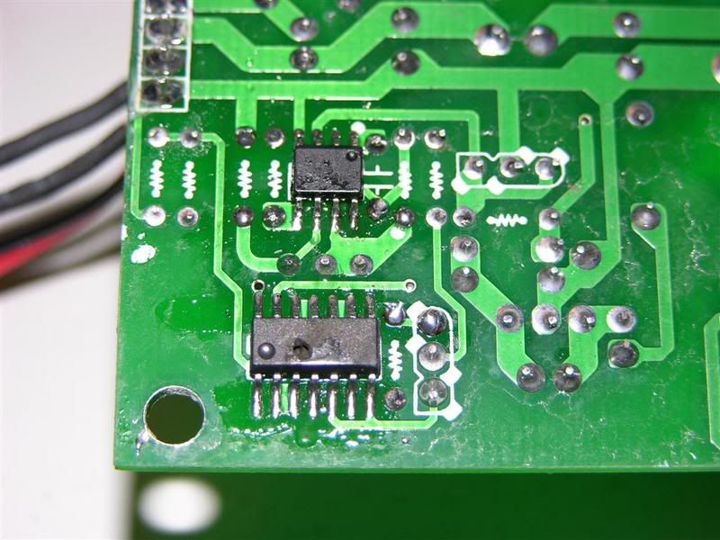
i put 240v to the TTL by mistake and bang!!!!!!!!!!!!!
can anyone help??????
this is the module#
http://www.laser-man.co.uk/2006/inde...d=38&Itemid=31
i think its the two chips on the botton that went bang
i put 240v to the TTL by mistake and bang!!!!!!!!!!!!!
can anyone help??????
this is the module#
http://www.laser-man.co.uk/2006/inde...d=38&Itemid=31
i think its the two chips on the botton that went bang
Eat Sleep Lase Repeat
Ouch... ZZZZZZZZaap...pop
I know that feeling.
If the supply part still works..and if your lucky nothing else went.
You could change-out the 14pin SMD ic , its most likely a 74hc08
The 8pin ic , is a probably a LM358
The dot and indentation indicates where pin 1 is.
Thats if your lucky thats all that happened.
"My signature has been taken, so Insert another here"
http://repairfaq.ece.drexel.edu/sam/laserfaq.htm
*^_^* aka PhiloUHF
Most likely, thats what I have been seeing from the import lasers.
closer, sharper pix will do it for me , as I can tell from the lay-out.
"My signature has been taken, so Insert another here"
http://repairfaq.ece.drexel.edu/sam/laserfaq.htm
*^_^* aka PhiloUHF
you can see a hole in the bigger chip LOL

Eat Sleep Lase Repeat
Ok, Im sure about the LM358..
I will study the circuit some more...
The other chips number doesnt look familiar, Altho Now I would probably say Itsa CD4011
used as an inverter or and gate to clean-up the logic and as a buffer too.
Last edited by marconi; 06-14-2007 at 10:22.
"My signature has been taken, so Insert another here"
http://repairfaq.ece.drexel.edu/sam/laserfaq.htm
*^_^* aka PhiloUHF
lol means nothing to me.
so are the def the chips i need to get???
Eat Sleep Lase Repeat
Hey Andy
I would pull the old chips off and measure the 5volt rail to see if its still there..if its not, that means the 220 made it to the diode driver , not good for the diode either..
An easy way to remove SM Chips is to use a good small iron and some solder-wick..however, me being a fast solderer, I have done it by small lifting pressure on the device while wetting one side at a time. getting all the pins on that side wet.then the other side.. they right pop off without damage.
Then solder-wick the remaining solder off the pads not too hard as to remove the pads.
Then to place the new chip in the correct spot, tack solder two corners..then solder all pins after your sure the chip is in the correct position. ,..note the DOT on the chip.
dont worry about too much solder at this point..using the tip of the solder-wick will clean that up.Just go slow and use a magnafying glass or scope to be sure no pads are bridged.
You can check the diode with a small regulated variable power supply..current limit it at 150ma.
If is one that doesnt allow adjustable current limit then just start at 0 volts and go very very slowly up to about 2v then a very tiny bit more...the diode should start to lase if its still good.of course be careful of polarity.
If all is good then I would look for the chips.
I still think the one chip is a cd4011 but could be a 4001.
I am sure about the op-amp.
someone else that has one could look for you..or ask the manu.
Digikey here in the states have what you need..I have sent you a PM on what part numbers you need.
..Good luck man
Last edited by marconi; 06-16-2007 at 13:47.
"My signature has been taken, so Insert another here"
http://repairfaq.ece.drexel.edu/sam/laserfaq.htm
*^_^* aka PhiloUHF
