

Hey,
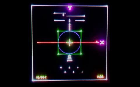
I'd like to share a few pictures of a recent projector build. A lot of the components were designed and built from scratch, so I figured some of you might find it interesting. This build is intended as a tabletop demo unit. The projector outputs roughly 750mW all single mode diode, but currently only scans 15k ILDA.
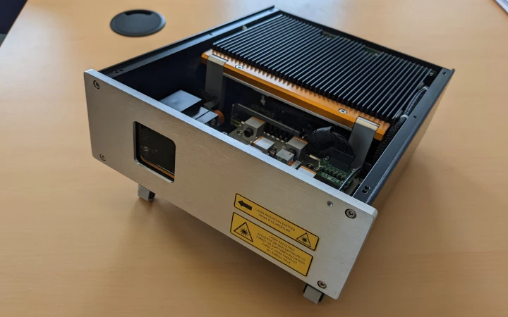
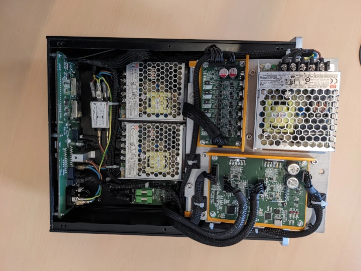
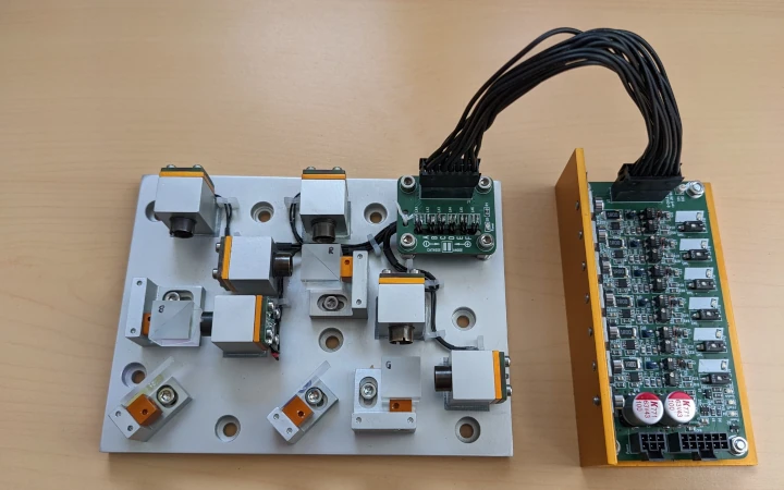
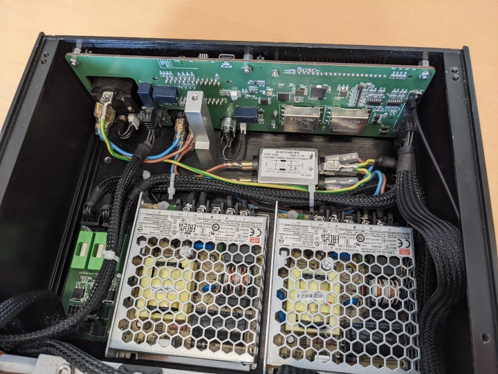
The electronics are mounted on a folding heatsink assembly. All trimmers, test points and the USB connectors for tuning the servo driver and scanguard (more on that later) are easily accessible. Cooling is completely passive, as I dislike noisy things on my desk.
Actuators
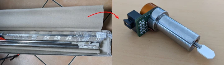
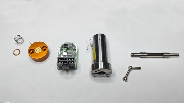
I built scanners mostly following the classic 1976 Montagu moving magnet design (U.S. patent #5225770A):
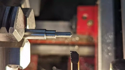
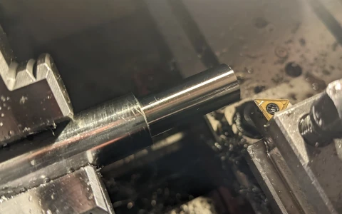
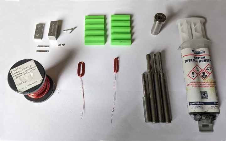
I used 4x20mm diametral N52 rare earth magnets that I found at a local art supply store. I ideally wanted to use 3x20mm magnets, but could not find anyone that would sell me a small quantity. I machined shaft segments from austenitic stainless (1.4301). The shaft was then mounted in the stator bore using 63 ceramic hybrid bearings. The bearings were arranged in X-configuration with axial preload. The rotors were glued using epoxy, since the shaft would plasitfy due to thin wall thickness before reaching the nescessary radial tension for a reliable press fit.
I machined interference fits between shaft segments and inner bearing races. During final assembly, the bearings were glued to the shaft to prevent interference corrosion induced by the motor's dynamic load point.
Since the motor does generate dynamic radial force, the outer load point is technically also dynamic and should be press-fit. Because this is not practical, I decided to use stainless steel for the stator and rely on axial preloading and a close fit to minimize movement. I chose a ferritic steel (1.4742) to reduce coercitive hysteresis and magnetic reluctance.
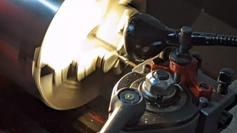
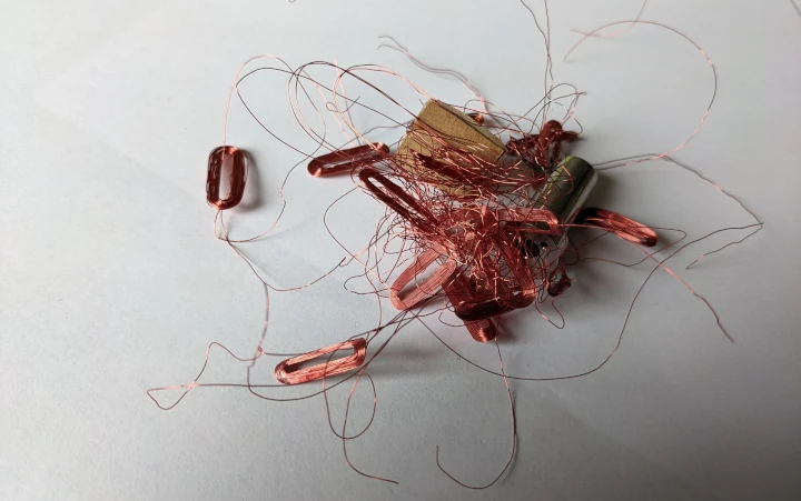
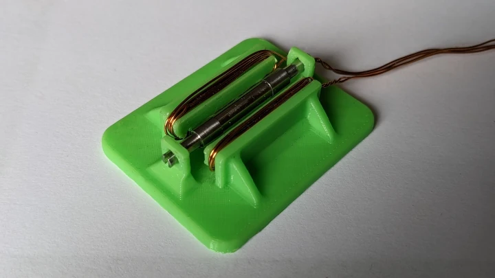
I hand-wound actuator coils from 0.2mm self bonding enamel wire. I machined custom tooling with different cores so I could adjust coil thickness to maximize packing density. After baking, the coils were pre-formed using 3D printed tooling and glued into the stator bore using thermal epoxy. Making and mounting the coils turned out to be the trickiest part of the build - after some attempts I machined more tools to help me position the coils while glueing. I heated the stators and epoxy before glueing to reduce viscosity and get better penetration into the actuator coils. This did however also reduce the epoxy's working time considerably. The wires were fed through a shaped slot in the stator bore:
Assembling scanners turned out to require some practise, in particular without shorting the coils to the stator:
Position Detectors
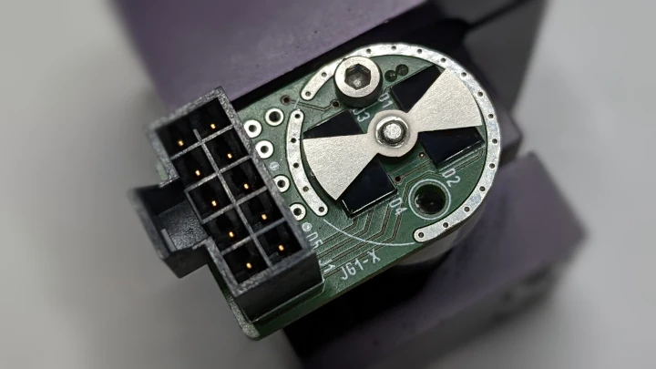
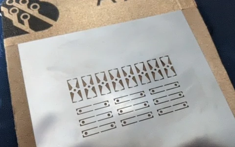
I built position detectors following Richard Ivers' 1997 design (U.S. patent #5844673A). Instead of specialized photo diodes, I used regular rectangular PDs I found online. I designed a small PCB for mounting the diodes. The rotating attenuator was made as a SMD stencil. The rectangular detectors result in non-trivial transfer characteristics. It does however archieve good linearity at +-15deg mechanical deflection, with singularities at large angles. The singularities can theoretically lead to loop instability, but were dealt with accordingly in software.
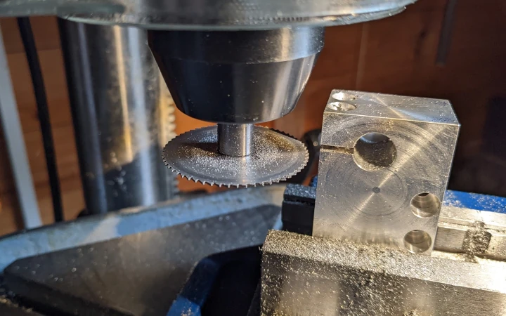
Jig for finding the rotor's magnetic poles before mounting the attenuator:
Servo Controller
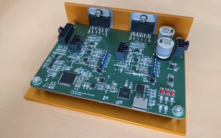
I designed a digital dual axis controller. I build TIA frontends with differential demodulators interface for the Photodetectors. PD gain is stabilized using closed loop control. The actuator coils are current mode controlled. Data is sampled at 200kHz/16bit with simultaneous sample and hold. The DAC also outputs 16bit at 200ksps. State derivatives are computed continuously, scaled and then sampled by the ADC to improve dynamic resolution. The controller runs PD or full-state-feedback control (which in this case are mathematically identical, but use different means to compute the gain matrix). Gain scheduling was implemented to compensate torque non-linearity (though this prooved not to be nescessary). Additional heuristic was implemented for self test, compensate previously mentoined singularities and prevent me from crashing the scanners too often. The scanners can be tuned using an on-board usb-serial bridge.
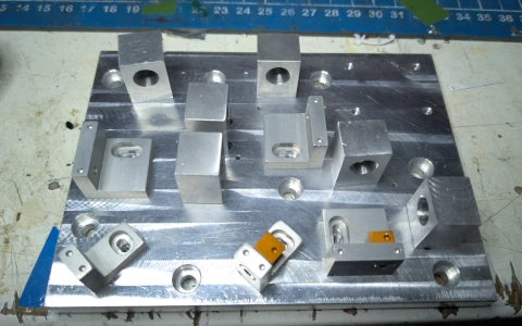
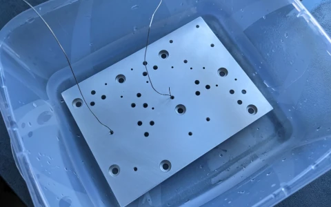
The mounting block was hand-machined:
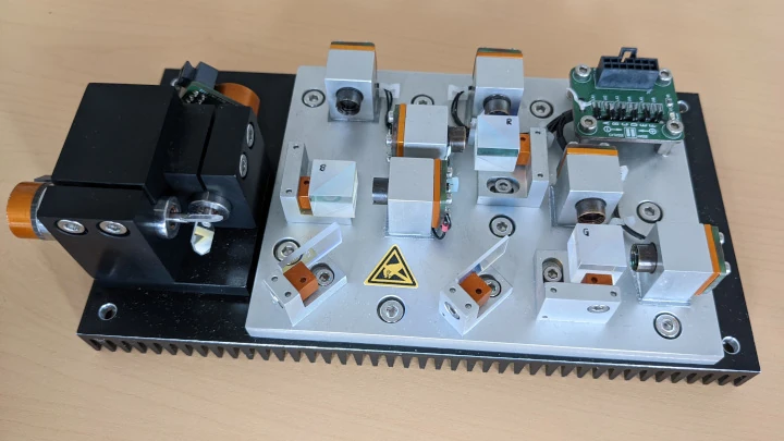
Optics
The projector outputs roughly 750mW. Diodes are all single mode:
1xGH0631IA2GC - 638nm/180mW
1xML101U29 - 658nm/150mW
2xPLT450B - 200mW 445nm
2xPLT520B - 220mW 520nm
(a setup that I stole from dkumpulas fantastic builds)
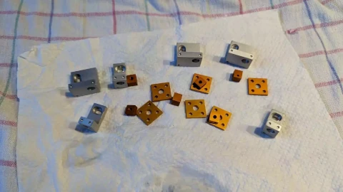
I machined diode and mirror mounts from 3.3636 aluminum. Beams are collimated using 3 piece lens assemblies and combined using PBS and diochroics. I added PCBs with ESD supressors to the diodes. The parts were anodized using my IKEA-Tank anodizing setup:
I designed a 6-channel low-side diode driver. It features standby supression, soft-start, power-supply watchdogs and a electronic shutter:
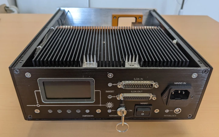
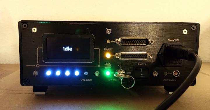
The ILDA interface board was scratch-build. TTL inputs are opto-isolated, so the entire connector can be ground-lifted. Shutter and interlock are daisy-chained using relay logic, also scramming any upstream projectors. X/Y can be inverted upstream. R/G/B and scanner feedback are monitored by a digital scan-guard setup, though I have not activated it at the moment. Laser emission can be stopped using the driver's shutter input. I also implemented ESTOP, startup delay, redundant case interlocks and emission indicators:
I would like to rant a bit about some things I did wrong in this build / do not fully understand / find interesting:
- My servo controller can become unstable if the negative supply rail ramps up before the positive supply:
This is because the CSAs I used for current sensing require the positive rail for defined output behaviour feeding into the power amps. Since I did not want to assemble another servo driver, I added a small PCB for power supply sequencing, that properly ramps the negative rail and disconnects power if one of the rails is not present.
- The detector's attenuator should ideally be keyed, so it can not rotate on the rotor shaft. Since I am relying on the attenuator to limit rotor motion, crashing the scanner breaks the glue joint.
- The mains filter is somewhat misplaced and probably messes with the PSUs PFC. I am not entirely sure why I thought it was a good idea to add it.
My motors scan aproximately 15k ILDA; this is slightly slower than what I wanted. I assume this is because:
- Use of 4mm magnets:
A 4mm magnet has roughly 500% more inertia than a 3mm magnet of equal length. This is somewhat mitigated by that fact that more torque is also generated due to higher magnetic flux. There is probably an optimum between torque eigen-frequencies, mirror inertia and magnet diameter, which, based on existing products, I would suspect to be near 3x20mm (for small beam steering). Because I did not have many choices in magnets, I did not consider this much.
There are some interesting considerations on torque estimation in Montagu's work on galvanometric scanners in the 'Handbook of Optical Scanning'.
- Current limiting in the motor driver (currently set to 5A pk.):
The driver was designed to deliver 10A peak or 8A rms. I wasn't brave enough to increase the drive current though, as any bug will annihilate the motors almost instantly at 10A.
- Velocity computation based solely on position derivative:
I did not implement 'high frequency damping', which makes it difficult to properly tune for ILDA transfer characteristics at righer scan rates. Though I have not found as much info as I would like on the theory behind HFD, I think this is because position deriative adds more phase than current integration. Because of this, the LFD term will not decrease fast enough when compared to the position error, resulting in undershooting the setpoint. If anyone has more info on this, I would be very interested. I suspect there is also a more practical explanation to this, as I could not observe the same behaviour in simulating the motors.
Since I do not sample motor current, an Observer-based aproach considering motor dynamics and the transfer characteristics of my current mode driver might improve this. I think the MachDSP amp uses a Luenberger-Observer, though using measured motor current and voltage to compute velocity, with drift compensation using position derivatives.
- The controller uses the infamous RP2040 125MHz Cortex-M0 processor without FPU. This is because at the time it was difficult to source DSPs (and I could not afford the devtools for a certain maritime-themed series of DSPs). The fixed point implementation and low instruction throughput made controller design more complex and prevented me from implementing more complex controllers.
I would like to increase scanning speed at some point. I am however somewhat statisfied with the build as it is right now.
Some Literature I found helpful (worth checking if you want to build your own scanner):
J. Montagu: Galvanometric Scanners in Handbook of Optical and Laser Scanning (G.F. Marshall, E. Stutz eds.) (more hands-on, also focusing a lot on non light show applications)
W. Benner: LASER SCANNERS: Technologies and Applications (nice overview to navigate scanner terminology and current products)
Advanced galvanometer-based optical scanner design by R. Aylward (mostly high level, with some interesting notes on torque calculation)
Cheers,
Jan


 Reply With Quote
 clickamouse


