Page 1 of 3 123 LastLast
Results 1 to 10 of 22

Thread: CX6325 amp for driving G120DTs

  1. #1
    Join Date
    May 2024
    Posts
    7

    Question CX6325 amp for driving G120DTs

    Hi everyone,


    I'm looking for some advice on driving 2 GSI Lumonics G120DT galvanometers which are inside a Nikon PCM2000 laser scanning head. I saw there was a thread from a few years ago where someone had a similar question (https://photonlexicon.com/forums/sho...T-Galvo-motors), and the GSI CX660 amp was recommended. In the manual, the compatibility chart shows that only the CX6120 version is used for G120DTs, but on eBay I can only seem to find CX6325.


    My question is: is it possible to adapt the CX6325 to drive G120DTs? If not, would anyone have recommendations for other potential drivers? My PI wants me to try the Cambridge Technology Dual Servo Driver 673, but I'm wary that the position feedback sensing is not compatible since the G120DTs are capacitive.


    I know it's an old piece of equipment so there's probably not an easy solution to drive it, but my PI would like to make use of this scan head if possible. Any advice or insight would be very much appreciated!


    Sheral

  2. #2
    mixedgas's Avatar
    mixedgas is offline Creaky Old Award Winning Bastard Technologist
    Infinitus Excellentia Ion Laser Dominatus
    Join Date
    May 2007
    Location
    A lab with some dripping water on the floor.
    Posts
    9,955

    Default

    Both of those amplifers you mention use the same motherboard... There are a series of low cost parts changed from unit to unit, and the rear connectors may be different, but the internals are all fitted the same with through hole components. Three digit part number is standard, four or more digits on a part means customized for needs of a client, or a new part number when incorporated into a product the vendor does not wish for the customer to be able to directly repair. When you see amplifiers in that distinct 19" rack scheme, I have never seen an optical feedback unit in that particular rack in 30 years.

    This link covers most of the changes. GSI made many custom units over the years, your part number reflects that customization.

    Hint, lift the Class AB output stage fuse to the Galvo coil, and troubleshoot accordingly with less fear of Galvo damage. Do not exceed 1.2 Amps peak to peak into the G-120 0r permanent demagnetization will result.

    When you can purchase decent Galvos from Dragon-Tiger, such as DT30, I question why you would want to use the G120 family unless they are already in an expensive confocal apparatus, have special mirrors, or extreme precision with existing software is required.

    Calibrating the feedback and using the AGC circuit is important.

    You may compare your motherboard to this drawing. Expect the external connectors to change, input levels to be single ended/ differential/ different, AGC to be on or off, and thermal blanket to be used/not used. For a confocal, thermal blanket is important if installed.

    chrome-extension://efaidnbmnnnibpcajpcglclefindmkaj/http://mavin.com/pictures/gl/gscan.pdf

    The chart in the back shows the parts changes vs galvo model.

    All changes are very subtle except in parts differences from G330 to G120. Even then some of the very slow G330 amps will "tune up" enough to run G120.

    Find a more modern galvo manual to help you learn how to tune the galvos for same speeds if the mirrors have differing inertia. Hint, detune the fast mirror to match the slow mirror on an oscilloscope. As this is a Laser Show forum what I just wrote will not make sense to those who use the ILDA Laser Show 24 or 30K tuning, that step is for the laser marking and microscopy industry when the Y mirror differs in size from the X mirror.

    Good Luck
    Steve
    Last edited by mixedgas; 05-29-2024 at 12:01.
    Qui habet Christos, habet Vitam!
    I should have rented the space under my name for advertising.
    When I still could have...

  3. #3
    mixedgas's Avatar
    mixedgas is offline Creaky Old Award Winning Bastard Technologist
    Infinitus Excellentia Ion Laser Dominatus
    Join Date
    May 2007
    Location
    A lab with some dripping water on the floor.
    Posts
    9,955

    Default

    DB15M connector
    Pin Number Wire Colour Signal Description
    1 Red Drive Coil (See notes 1 & 2)
    2 Yellow Drive Coil (See notes 1 & 2)
    3 Black Position output (-)
    4 Orange Position Output common
    5 Red Heater - T-Type (See note 3)
    6 N/C No Connection
    7 Red Heater - T-Type (See note 3)
    8 White Oscillator supply voltage (+)
    9 Green Drive Coil (See notes 1 & 2)
    10 Black Drive Coil (See notes 1 & 2)
    11 Red Position Output (+)
    12 Violet AGC
    13 Brown Oscillator supply voltage common
    14 N/C No Connection
    15 Blue Thermistor - T type (See note 3)
    NOTES
    1/ To wire drive coils in series, connect Black to Green and drive Red to Yellow. Series wiring is recommended for use in position sensing (closed loop) mode.
    2/ To wire drive coils in parallel, connect Red to Green and Black to Yellow. Use parallel wiring only when driving the galvo in open-loop mode.
    3/ Heater blankets are mounted only on the G120DT type galvos and are not commonly used in light show applications.
    Qui habet Christos, habet Vitam!
    I should have rented the space under my name for advertising.
    When I still could have...

  4. #4
    mixedgas's Avatar
    mixedgas is offline Creaky Old Award Winning Bastard Technologist
    Infinitus Excellentia Ion Laser Dominatus
    Join Date
    May 2007
    Location
    A lab with some dripping water on the floor.
    Posts
    9,955

    Default

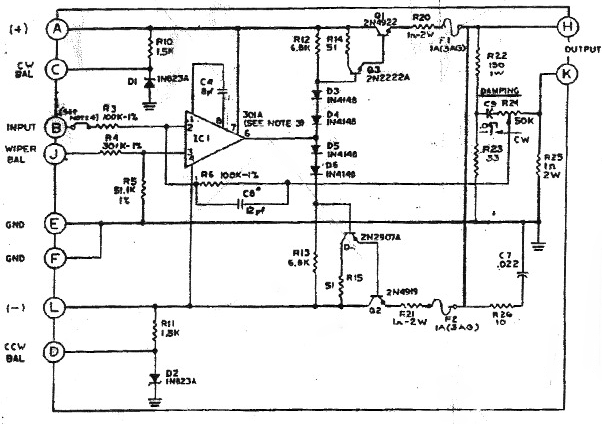
    Derived feedback amplifier for bench testing G120, Damping only, does not use position sensor, included as an aid to understanding for a tech. AKA GSI A-102 or A-106.


    A +V [usually 15-28 VDC]
    B Scan Signal Input
    C External Offset Potentiometer (10K) CW
    D External Offset Potentiometer CCW
    E Ground
    F Ground
    H Galvo Output
    J External Offset Potentiometer Wiper
    K Galvo Output
    L -V [usually 15-28 VDC]
    Last edited by mixedgas; 05-29-2024 at 15:45.
    Qui habet Christos, habet Vitam!
    I should have rented the space under my name for advertising.
    When I still could have...

  5. #5
    mixedgas's Avatar
    mixedgas is offline Creaky Old Award Winning Bastard Technologist
    Infinitus Excellentia Ion Laser Dominatus
    Join Date
    May 2007
    Location
    A lab with some dripping water on the floor.
    Posts
    9,955

    Default

    Technoroam's G120 page.

    http://www.technoroam.sk/lasershow/

    If you have to build one type pf g120 amplifier, build this:

    http://www.technoroam.sk/lasershow/d...120Amp_SCH.pdf
    Attached Files Attached Files
    Last edited by mixedgas; 05-29-2024 at 15:17.
    Qui habet Christos, habet Vitam!
    I should have rented the space under my name for advertising.
    When I still could have...

  6. #6
    mixedgas's Avatar
    mixedgas is offline Creaky Old Award Winning Bastard Technologist
    Infinitus Excellentia Ion Laser Dominatus
    Join Date
    May 2007
    Location
    A lab with some dripping water on the floor.
    Posts
    9,955

    Default

    CX 660 Cx-660 CX660 General Scanning Manual is attached.

    Most of the CX family on Ebay will be fixer-uppers, assume you will need a technician to repair it.

    Find CXs with DB15 connectors on the back, unless your galvo pair has the long outdated blue circular mini connectors, in which case run away from this project NOW.

    If you have a good technician, built the Technoroam amp below on a PCB . You'll be happier, it has a better seek time, and not be hunting down hard to find transistors if something is wrong.

    You'll have to do some digging, but Howard Hughes Janelia Research campus once offered DIY confocal design plans for everything, including freeware code. There is other free software out there, so you do not have to program in Labview, trying to make images with home-made code is graduate career death, a tough distraction.

    The file below has the table for changing feedback loop parts.


    I spent six years nursing an old Olympus FX-1000, and training students thereof, I know of what I speak.

    DO NOT EVER twist the G120 shafts by hand, you will break the Torsion Bar.

    Where are you located at?

    The past project you linked ended badly for the student. He hurried, and failed. I then sent him a similar replacement amplifier for free, he destroyed it. Analog Electronics requires extreme patience and practice, and some common sense. Galvos require even more thinking before you move. I could not help him from the Midwest when he was on the West Coast.

    That student used jumper clips instead of properly constructed cable connections to the old hardware. It destroyed the system output card and the galvo amps as he chose AC frame ground from the controller instead of analog LV circuit ground. Take the time to find the signal paths with an oscilloscope, very carefully.

    The next issue will be tuning the galvo PID to match the software's desired seek time parameters. You can tune the amplifer loop for speed, accuracy, or a lessor combination of both, be underdamped with ringing, damped properly or overdamped. A good dual trace oscilloscope is essential. Preferably an analog scope.


    Steve
    Attached Files Attached Files
    Last edited by mixedgas; 05-29-2024 at 16:03.
    Qui habet Christos, habet Vitam!
    I should have rented the space under my name for advertising.
    When I still could have...

  7. #7
    Join Date
    May 2024
    Posts
    7

    Default

    Hi Steve,

    Much thanks for all the advice and information, I truly appreciate you spending the time to explain all this! We're located at the University of Toronto in Ontario, Canada.

    We got this scan head second-hand for our confocal setup and it originally came with the G120DT galvos inside. As we haven't been able to drive them, we don't even know if they are in working condition. We haven't yet purchased a CX660 from eBay, but it is fantastic to know that the information to modify it is all there in the manual (although it sounds like the replacement parts might be hard to come by?). Thanks as well for your alternative schematics, these will be quite handy for testing if we go down this route, to see if the galvos even work in an open loop config. I have some experience with analog electronics but that was at an undergrad level and not with scanning systems, so I will have to take my time if we decide to go this way.

    I appreciate the freeware tip as well-- I'm trying to avoid using LabView in general as our setup is so customized, so I've been digging for open-source software / code inspiration.

    My group is also considering fully replacing the galvos with a newer model, which I think will save us a major headache in the long run. But we need to find ones that will fit in the scan head and have the required frequency that come with mirrors that will reflect our wavelengths and withstand the OPD of the lasers. Fingers crossed...

    Sheral

    Quote Originally Posted by mixedgas View Post
    CX 660 Cx-660 CX660 General Scanning Manual is attached.

    Most of the CX family on Ebay will be fixer-uppers, assume you will need a technician to repair it.

    Find CXs with DB15 connectors on the back, unless your galvo pair has the long outdated blue circular mini connectors, in which case run away from this project NOW.

    If you have a good technician, built the Technoroam amp below on a PCB . You'll be happier, it has a better seek time, and not be hunting down hard to find transistors if something is wrong.

    You'll have to do some digging, but Howard Hughes Janelia Research campus once offered DIY confocal design plans for everything, including freeware code. There is other free software out there, so you do not have to program in Labview, trying to make images with home-made code is graduate career death, a tough distraction.

    The file below has the table for changing feedback loop parts.


    I spent six years nursing an old Olympus FX-1000, and training students thereof, I know of what I speak.

    DO NOT EVER twist the G120 shafts by hand, you will break the Torsion Bar.

    Where are you located at?

    The past project you linked ended badly for the student. He hurried, and failed. I then sent him a similar replacement amplifier for free, he destroyed it. Analog Electronics requires extreme patience and practice, and some common sense. Galvos require even more thinking before you move. I could not help him from the Midwest when he was on the West Coast.

    That student used jumper clips instead of properly constructed cable connections to the old hardware. It destroyed the system output card and the galvo amps as he chose AC frame ground from the controller instead of analog LV circuit ground. Take the time to find the signal paths with an oscilloscope, very carefully.

    The next issue will be tuning the galvo PID to match the software's desired seek time parameters. You can tune the amplifer loop for speed, accuracy, or a lessor combination of both, be underdamped with ringing, damped properly or overdamped. A good dual trace oscilloscope is essential. Preferably an analog scope.


    Steve

  8. #8
    mixedgas's Avatar
    mixedgas is offline Creaky Old Award Winning Bastard Technologist
    Infinitus Excellentia Ion Laser Dominatus
    Join Date
    May 2007
    Location
    A lab with some dripping water on the floor.
    Posts
    9,955

    Default

    I'm in Ohio... I keep a few g120s laying around, if need be.

    Steve
    Qui habet Christos, habet Vitam!
    I should have rented the space under my name for advertising.
    When I still could have...

  9. #9
    Join Date
    May 2024
    Posts
    7

    Default

    Quote Originally Posted by mixedgas View Post
    I'm in Ohio... I keep a few g120s laying around, if need be.

    Steve
    Hi Steve,

    The scan head we have came with a MicroMax ST-133 5MHz unit, which I believe they intended on using to drive the galvos. It's made for use with particular cameras, not for scan heads (which makes it odd that it came with the scanner). Have you ever seen something like this be used as a controller? I've attached the manual.

    My PI also wanted me to ask whether you would be willing to build an amp for us (whether that be the custom one you linked or from adapting a CX-660), and if so, what your prices are.

    All the best,
    Sheral
    Attached Files Attached Files

  10. #10
    Join Date
    Sep 2014
    Location
    Colorado USA
    Posts
    866

    Default CX-660's

    I just realized after reading this thread last month) that I know where a brand new, unused but stored for decades) pair of these are if anyone is interested.

    Click image for larger version. 

Name:	20220427_154352.jpg 
Views:	4 
Size:	4.53 MB 
ID:	61202

    PM me and I will see if they are still available...most likely are.
    ________________________________
    Everything depends on everything else

Posting Permissions

  • You may not post new threads
  • You may not post replies
  • You may not post attachments
  • You may not edit your posts
  •