ok a task for tomorrow night
cheers

 Senior Member
ok a task for tomorrow night
cheers
Eat Sleep Lase Repeat
Senior Member
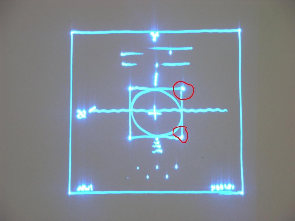
just to confirm your talking about over shoot here??
Eat Sleep Lase Repeat
Senior Member
If the image you were projecting came out upside down, what would you have to do to correct it?
Senior Member
Either flip it in the software or swap the wires on the Y axis to the drivers
Yeah, that's overshoot Andy. You're on the right track.
Also, Graham - to expand on what Mliptack said; if the pattern is upside down you can usually flip the pattern by changing a set of jumpers on the scanner amp. This is the usual method used to invert the pattern. However, you can also flip it in software. (Changing the orientation of the scanner mounting block will work too!)
But swapping the input wires around won't always work. If you are using a single-ended connection to your scanners, swapping the input wires on one amp may actually create a short to ground (through the scanner power supply).
Adam
Senior Member
ok will have a look wheni get home from work.Originally Posted by Buffo

Eat Sleep Lase Repeat
Member
I've seen something like this ( high frquency noise on one of the axis) . After spending ages re-tuning the driver, the solution turned out to be moving the driver card further from the grounded metal chasis. When there was 8mm or less between the solder side of the board and a ground plane, there was instability on one axis (but not the other ??) when displaying some images. Increasing the gap to 20mm stopped the problem entirely. Must be some of the sensitive signals on the driver board being capacitivly coupled to ground.
B.
Hi Fuzcub; welcome to PhotonLexicon.
I'm intrigued by your solution to the HF noise problem... Thanks for sharing that info! Out of curiosity, what type of scanners were you using when you experienced this problem?
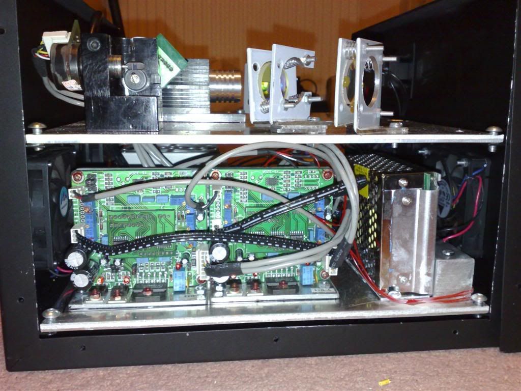
I'm assuming that you had your amps mounted horizontally.?. (that is, with the solder side of the board parallel with the baseplate of your projector) I normally mount my scanner amps in the vertical position to make it easier to get at the tuning pots from the side or back of the projector. But I don't know how Andy has his mounted. (Can't view his pics at work; they're blocked by the firewall.) It would be interesting to find out if he does indeed have them mounted horizontally, and if so, whether they are close to the baseplate or not.
Who would have thought that simply increasing the air gap between the amp and the baseplate would make such a difference?
Adam
Last edited by buffo; 01-24-2008 at 05:32.
Senior Member
i had the same problem in my wooden housing
Eat Sleep Lase Repeat
Member
Thanks for the welcome Buffo,
This occurred during a repair of a popular brand of chinese laser - the driver boards looked identical to those supplied with scanpro 30k/40k scanners. The drivers were mounted onto the baseplate , and screwed down through the adjustable slots in the heatsinking plate.
I had moved the drivers to make the pots more accessible , but this decreased the gap between the back of the board and a metal divider inside the case. After lots of cable swapping, scanner swapping and chin scratching I could only get it to work properly if the drivers were removed from the case. Until I noticed that I could reproduce the problem by waving my earthed hand over the underside of the board. My guess is that the tolerance of some of the small value capacitors buried in the feedback/PID section of the circuit might have been right on the threshold of not quite working as they should. Or it might have been a dry joint somewhere.
I can see from Andy's photo that his drivers appear to have a ground plane built onto the heatsink plate, so I don't think my theory sticks.
Other things might be a magnetic/electric field being radiated by the fan(left), or switchmode powersupply(right) . There could be HF ripple on the power supply rails (but that should effect both axis)
B.

 Posting Permissions

 Reply With Quote
 buffo
buffo