Page 1 of 3 123 LastLast
Results 1 to 10 of 29

Thread: RGB progress - slow & painful...

  1. #1
    Join Date
    Jul 2007
    Location
    Knoxville, TN, USA
    Posts
    3,154

    Default RGB progress - slow & painful...

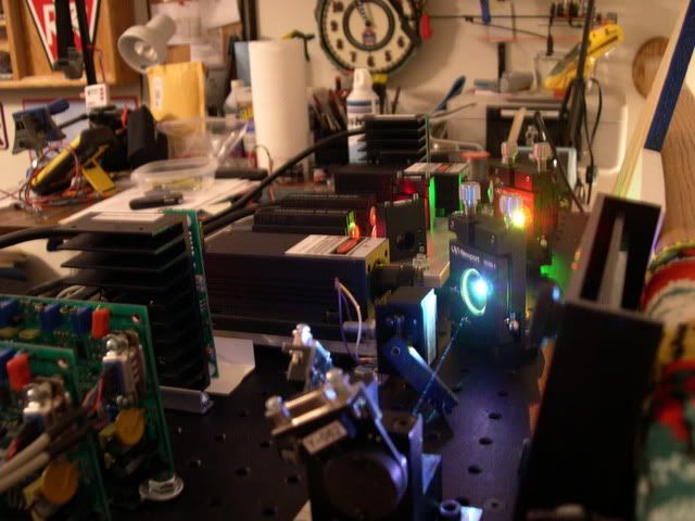
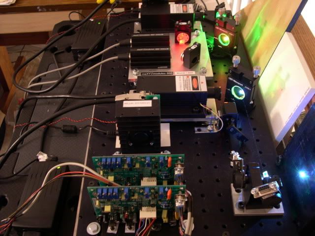
    First shots of my first RGB projector in progress.

    SLOW progress (frickin' shame we have to work for a living), but it's getting there. Attempted to assemble everything without drilling any additional holes - and am quickly finding out that probably doesn't work very well, even with a predrilled breadboard!!

    400mw CNI 532 nm, dual Maxyz 660 nm, and 150 mw CNI 473nm, feeding a set of ScanPro 30's, all at full power - color balance comes later!


    RR

    Metrologic HeNe 3.3mw Modulated laser, 2 Radio Shack motors, and a broken mirror.
    1979.
    Sweet.....

  2. #2
    Join Date
    Oct 2006
    Location
    Central Florida
    Posts
    7,067

    Thumbs up Well done!

    NICE!!! 100xs better than my first go! Be proud. Must be all that work under pressure you have done for all of us. Actually a good 10xs better than my current set up. What do you mean slow... Looks like all you got to do is to hook up them scanners and you're off.
    Love, peace, and grease,

    allthat... aka: aaron@pangolin

  3. #3
    Join Date
    Sep 2006
    Location
    St. Louis, MO - US
    Posts
    83

    Default

    Mmmmm...photos...I love photos of laser equipment...especially when there is a bread board table involved.

    Looks fantastic! Hook up those scanners! Hurry!


    Phil


    my RGB is pretty big dipper looking...cause they made it...

  4. #4
    Join Date
    Jan 2006
    Location
    Charleston, SC
    Posts
    2,147,489,459

    Cool

    Nice work, Randy! You've done a great job of aligning everything!

    Will you have a separate level below the optical plate for your power supplies, or do you plan to mount them behind the optical table? What will the final housing look like?

    Adam

  5. #5
    Join Date
    Jul 2007
    Location
    Knoxville, TN, USA
    Posts
    3,154

    Default

    Thanks for the kind comments everyone!

    Hey, Adam!

    I'm still planning on a double-decker design, with the power supplies and support electronics on the lower shelf. I hope to keep everything as compact as possible.

    As far as the final design goes - well, what I want to include in the projector seems to change everytime I work on it (which is not near often enough!), so at this point we'll just say that the "final design" is also "work in progress"...

    I brought the magic laser footlocker with me to Ft. Eustis, VA (I'm here until early April), so hopefully I'll make progress on the electronics while I'm here. Hopefully, more work-in-progress photos to post soon!!

    Randy
    RR

    Metrologic HeNe 3.3mw Modulated laser, 2 Radio Shack motors, and a broken mirror.
    1979.
    Sweet.....

  6. #6
    Join Date
    Nov 2005
    Location
    Melbourne, Australia
    Posts
    3,702

    Default

    Looking good Randy!

    Yeah, nothing ever seems to fit a pre-drilled beam table, I guess the problem is you Americans use all these weird size screws and bolts I personally prefer just getting a 10mm slab of aluminium, and drilling/tapping the holes I need.. As long as the measuring up is accurate, this way tends to work a lot better, and can be made more compact as well

    Keep up the good work

    [edit] it would be worth replacing the cni switchmode psu's with a nice big open frame psu.. We have been using XP power supplies for everything and love them
    KVANT Australian projector sales
    https://www.facebook.com/kvantaus/

    Lasershowparts- Laser Parts at great prices
    https://www.facebook.com/lasershowparts/

  7. #7
    Join Date
    Jul 2005
    Location
    Flying over a town near you
    Posts
    1,404

    Wink

    Amen on drilling holes in Alu stock! Layout all lasers and optics, fire up, adjust, mark and drill/tap. Done. Almost done with RGB #3. It has worked seamlessly every time. Pix soon.....
    You are the only one that can make your dreams come true....and the only one that can stop them...A.M. Dietrich

  8. #8
    Join Date
    Apr 2007
    Location
    Toronto Canada
    Posts
    1,120

    Default

    Drill/Tap for me as well.
    I hired an Italian guy to do my wires. Now they look like spaghetti!

  9. #9
    Join Date
    Mar 2007
    Location
    Rotorua New Zealand
    Posts
    528

    Default

    Drill and tap a term indicating great engineering precision..
    Also a real pain the rear end as it takes so long... if you do it right that is.

    However as most times we are doing this to screw "things" down to the base plate and high precision is a secondary consideration I have found that a good way to speed things up is to drill the pilot hole (which you have to do anyway) then fit your tap to your variable speed battery drill .... ( geeeezuz!! I can hear all the real engineers yell from way down here).

    Go at a slow pace and you have nice taped holes in no time flat. Don't forget a drop or two of cutting oil to avoid spalling and jamming. Keep a steady hand on the drill and don't push it, just kinda let it happen.

    I found this made a hell of a speed change. When I did my first greenie I did it "properly" with T handle the lot.... back and fore etc etc..hours of work.. no need for this type of job.

    I'm sure some of you already know this but if not give it a go you'll be suprised just how much faster it makes the job go.

    Cheers

    Ray
    NZ

  10. #10
    Join Date
    May 2006
    Location
    Native Floridian
    Posts
    3,128

    Default

    Holy Cow! Very nice work Stuka! Can I asume you will be joining us at SELEM?!?! Let see, FLEM we had 4 working RGB rigs, so for SELEM, I think we may have around 6 or more!

    David

    ps-I like those newport mounts! Not cheap, but whole lot easier to do alignments...

Posting Permissions

  • You may not post new threads
  • You may not post replies
  • You may not post attachments
  • You may not edit your posts
  •