you wouldnt happen to have the scan linearizer board for the 4K resonant scanner would you?
Steve

 Creaky Old Award Winning Bastard Technologist
you wouldnt happen to have the scan linearizer board for the 4K resonant scanner would you?
Steve
 Senior Member
Forgive my inexperience, but what would that be, where would it be located? I know the drive for the res. scanner is on the same board. You can see the socket for it between the heatsink and the two trimpots. What does the linearizer board do? Is it a 4KHz signal generator?
If you're the smartest person in the room, then you're in the wrong room.
Senior Member
I have gotten it a little better. This is as close as I can get. 15K at 8 degrees.

If you're the smartest person in the room, then you're in the wrong room.
Creaky Old Award Winning Bastard Technologistit takes the 4Khz sinewave feedback signal from the resonant scanner and converts it into a equally spaced linear pixel clock for the writing or scanning laser beam or photodetector. Ie it makes variable timing square waves to get you equal spaced pixels. Its quite a big board and GSI only sells them matched to a scanner. I have a 4 khz resonant scanner thats actually the 15,570 hz horizontal video scan rate divided by 4 = 3892 hz, so you run 4 beams off the same mirror in a array, you get a ntsc video signal. You hook the linearizer board's pixel clock to a frame memory and you get laser video.Originally Posted by absolom7691

Steve
Creaky Old Award Winning Bastard TechnologistIf you had blanking thats actually not a bad ILDA pattern. your a tad overdamped.
Steve
Senior Member
I might have the board that you speak of. Let me look around. I still have all of the boards and tidbits from this unit. let me dig around and I'll post some pics and maybe you could identify it.
I am working on blanking with my modded sound card right now. For the time being, I am only using a 2mW green-Ne so, no blanking without a Z axis or AO mod. If I were to use my 200mW Green, even with the ISO set to 100 and my camera stopped down to f32, I think it would still be too bright given the length of the exposureto capture the whole image. Oh well. Once I get the blanking channel finished on my correction amp, hopefully this will look better. I trust blanking will take care of the ugly retrace lines on the circle.
Thanks again Steve for all your time and suggestions. Everyone here at PL has been so helpful!
If you're the smartest person in the room, then you're in the wrong room.
Senior Member
Okay, I got the blanking circuit done on my correction amp. I tweaked my amps a bit more and finally got the circle to touch the square. I am noticing bad artifacts on the blanked dots and lines. At least I am moving in the right direction. I am still not sure which pot does what, which is why I am still seeing undershoot on the little square.
It is clear by the circle that these are doing way better than 12k:
At 15k, the circle looks right, but the blanking looks terrible. Is this a blanking problem (latency?) or is this a problem with the scanners' tuning?:
18k was just wishing thinking. I am going to keep trying though. I think I can squeeze 18K out of these. I just need to get the pots figured out:

If you're the smartest person in the room, then you're in the wrong room.
Creaky Old Award Winning Bastard Technologistlooks like jellybeaning a bit (small blanking problem)
Steve
Senior Member
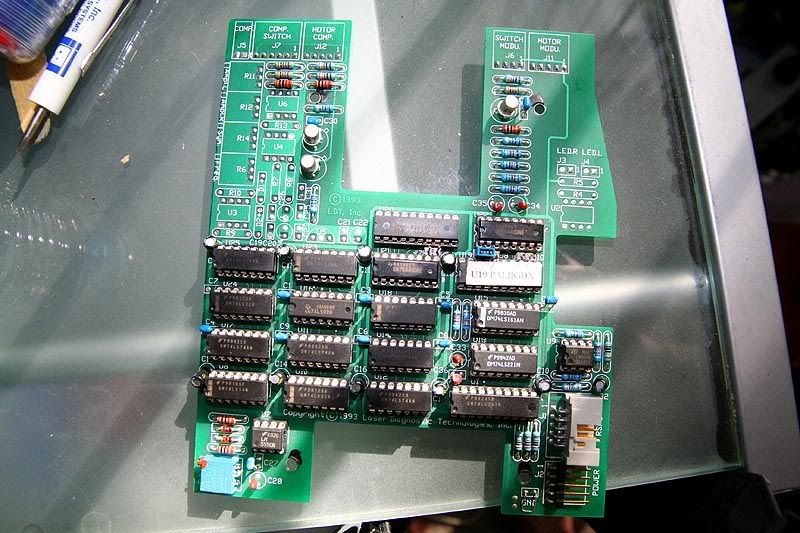
being new to ttl blanking, how can I fix this problem?
BTW, is this the board you were speaking of, for the res scanner?:
If you're the smartest person in the room, then you're in the wrong room.

 Posting Permissions

 Reply With Quote
