Is the laser on when its input is floating? If not? Does a 10K ohm resistor tied to plus 5 source enough current to turn it on?
Steve


 Creaky Old Award Winning Bastard Technologist
Is the laser on when its input is floating? If not? Does a 10K ohm resistor tied to plus 5 source enough current to turn it on?
Steve

Steve,
Neither Laser-Wave or CNI lasers are on when the analogue mod input is floating. I think you see that more in cheap Chinese TTL lasers..
Anyway, I just did some tests with a Laser-Wave 1w, and a CNI 200mw I have here waiting for use.
The laser-Wave pulled about 5ma from the mod input, and the CNI pulled about 3ma from the mod input. Both too much for the poor little processor output.
So much for high impedance inputs eh! I have never noticed this here before, as we have a small board with a differential receiver for the colour channels on all our lasers, so its never been a issue for us here..
Originally Posted by mixedgas

KVANT Australian projector sales
https://www.facebook.com/kvantaus/
Lasershowparts- Laser Parts at great prices
https://www.facebook.com/lasershowparts/
 Member
I'm going to head over to radio shack after work today and see if they have one of those op amps.
I'm not an EE, I just know the basics, so let me know if I'm understanding this right; the op amp will step up the current while keeping the voltage the same?
Creaky Old Award Winning Bastard Technologist
yes, get yourself 2 9V battery clips and a Tl082 or 741 opamp.
Also a 330 ohm resistor to protect the laser if the opamp goes squirlley.
Steve
Member
Alright so I went out and bought the components as Dave and Steve suggested. Got me a 741 op amp, some resistors, and some battery clips. Unfortunately, I'm not having much luck getting it to work. I've breadboarded up the circuit and tested it to no avail.
Since I probably wired it up wrong, let me tell you what I've got and maybe you can see my mistake;
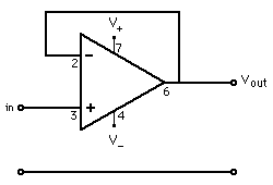
Following Daves diagram and pin numbers above, I've got pin 6 shorted to pin 2, mod+ from the scanner hooked up to pin 3, mod+ to the laser hooked up to pin 3, and the mod GND hooked directly to the laser's GND (same as the mod).
I wasn't sure whether I needed to supply outside power to the op amp itself but I tried it that way and a few different other ways, none seem to work. Any idea what I should have hooked up to pin 4 and 7?
Thanks!
pin 3 goes to the program board output
pin 6 goes to the laser mod input
the power - its probably easiest to wire these up to the positive and negative rails of the scanner power supply
KVANT Australian projector sales
https://www.facebook.com/kvantaus/
Lasershowparts- Laser Parts at great prices
https://www.facebook.com/lasershowparts/
Member
I've tried hooking up external 5v to the op amp (pins 4 and 7)... Are you saying I should use the 15v source for the scanpro set? Will that damage the op amp? Like I said, I don't know a lot about electronics, I just want to make sure I'm understanding you right before I blow something up
Thanks!


You need more than 5 volts to make it work. Connect the +15 volts from your scanner psu to pin 7, and connect the -15 volts from your scanner psu to pin 4, and it should work. (Don't worry, the 741 op amp is designed for +/- 18 volts on the power inputs.)
Adam
Member
Hi again everyone. First off, I'd just like to say how much I appreciate everyone's help! And not just on this issue, but my whole experience in the world of lasers. Thanks!
So on to my update. I believe we're closer... but still not there. With 15v from the scanpro PSU applied to the op amp, the laser does indeed light up to full power when the rig is turned on. Problem is, it doesn't blank at all. In fact, the laser is completely consistent at full-on regardless of what random patterns I feed it.
If I disconnect the mod from the scanpro board, it turns off.
Any ideas?
I dont suppose you have access to an oscilloscope?
KVANT Australian projector sales
https://www.facebook.com/kvantaus/
Lasershowparts- Laser Parts at great prices
https://www.facebook.com/lasershowparts/

 Posting Permissions

 Reply With Quote
 dave
dave