Second drlava's mods, they made all the difference for me esp with the color signals converted to single ended when using the elos plug.

 Senior Member
Second drlava's mods, they made all the difference for me esp with the color signals converted to single ended when using the elos plug.
leading in trailing technology
Senior Member
Anyone looking for the images that are missing above:
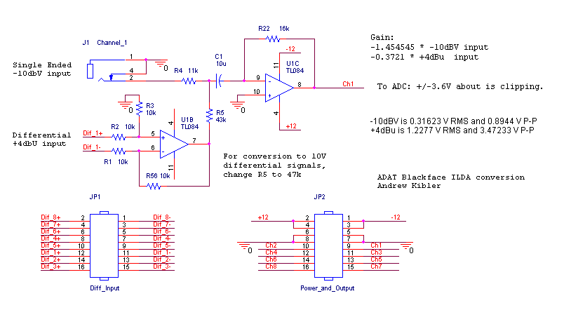
https://innolasers.com/laser/ADAT/Input.png
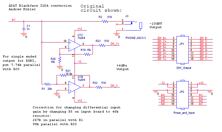
https://innolasers.com/laser/ADAT/Output.png
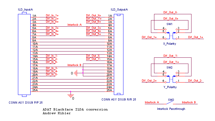
https://innolasers.com/laser/ADAT/Connectors.png
I also mirrored them at users.757.org/~ethan/pics/geek/lasers
Senior Member
I 'fixed this up' a little:
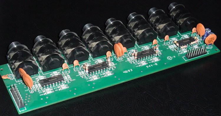
Modification on the input board: Beyond the DC coupling modification described in the link above, the R5 resistor of channels 1 and 2 (X and Y) can be changed to 47k. (In my case 46k was the resistors measured value)
Input:
Modification on the output board: This board comes DC coupled, but you need to compensate for the gain change performed in the last step. For channels 1 and 2, place 267k parallel with R1 and 98k parallel with R20. Now, For this project I decided to make the RGBI channels single ended instead of differential to be compatible with both differential projectors and single ended projectors that expect 0-5V modulation input. This should make it more universally compatible with existing projectors with and without differential inputs. For this mod, place 7.74k parallel with R20 on channels 3,4,5 and 6. I reached 7.74k using specially selected 1k and 6.7k resistors in series. For safety, I recommend adding a voltage clamping circuit to this output so that your modulation voltages will not exceed 5V.
Finally, when wiring up the output, if you did the single ended modification, ground the RGBI- outputs, or if you did not, connect these to the 3,4,5,6- differential outputs.
Output:
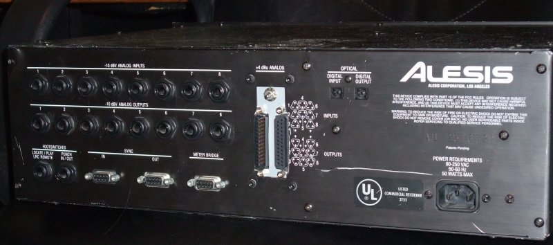
Ilda Connectors:
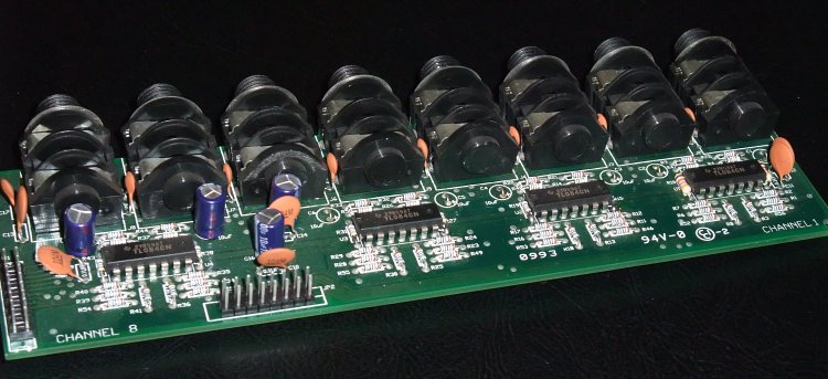
Result:
Input Board:
Output Board:
ILDA Connectors:
Last edited by LaserCo; 03-22-2015 at 04:03.
Senior Member
Regarding the input stage, C1 should be shorted. Regarding the output stage, this isn't all that's required to modify a black face for dc output, there are a number of caps on the card behind the input output card that need to be shorted. Plus the single to differential converter could be improved. And on the color channels (3, 4 and 5) I would include clamping diodes.
Senior Member
So I decided to try to get the pile I have running. Went from 1 working machine (tape mech) to 3 working machines.
I then proceeded to modify one using the Pangolin docs, although I did one change. I pulled off one side of a resistor and ceramic cap on channel 1 and 2 to disconnect the tip on the 1/4" and tied those to the + side
of the 1/4" on 1 and 2 so I don't have to touch the elco (this is for output only.) Hopefully the pluto2 will be okay with the GND to +10 fed to it as -5 to +5 on X and Y.
I don't know why but I've always thought the ADAT machines (and the DA-88/DA-38/Sony PCM-8000) were neat, even though tape is crusty. Years ago a friend had a home studio with 3 XT models or something and was doing some amazing work with them.
Here is a video I threw together of cleaning the black ADAT machine to get rid of Error 7s (Er 7), as well as the fix for Error 9 (Er 9) which is when tape spools out and gets all jammed in there. The cleaning was a success.
https://www.youtube.com/watch?v=P-XVXGUhC-Q
Enjoy.

 Posting Permissions

 Reply With Quote