Yip same here, no change whatsover.Originally Posted by sbk


 Senior Member
Yip same here, no change whatsover.
Doc's website
The Health and Safety Act 1971
Recklessly interfering with Darwins natural selection process, thereby extending the life cycle of dim-witted ignorami; thus perpetuating and magnifying the danger to us all, by enabling them to breed and walk amongst us, our children and loved ones.
Senior Member
Hi all,
Just a few quick points:
LAStudio will "interpret" a frame as vector-oriented unless you tell it not to. Normally that is beneficial for frames you'll generally find floating around in libraries. LivePRO will also interpret imported frames as "vector oriented" by default. After importing a frame into a cue, you need to select Cue Properties and tell it that you want it interpreted as point-oriented. (Vector-oriented frames have rules which are above and beyond those of point-oriented frames. There are "environment settings" that control this...)
A circle drawn with any Pangolin software will naturally have blanking to it, because there is an overlap and we maintain beam velocity while the beam is off. So a circle is not a very good test case. Dave Zurchur's test frames are good candidates because they themselves do not have any blanking.
We're still performing side-by-side tests with QM2000 and FB3. At this point we can say -- for sure -- the voltage level itself goes all the way up to 5 volts for both. As for the duty cycle, we're still looking into this.
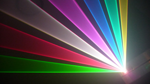
Ante has sent this scope photo for the QM2000. This is exactly as expected:
LD300.bmp
A 300 point frame becomes 323 points, out of which the 300 are "high" -- so 300/316 = 94.9% duty cycle. Remembering that the eye sees 0.2x the BEAM power appears to the eye as "half as bright" , 92.9% of the beam power should have brightness implications that are imperceptable to the human eye.
So with a single point, the story is (of course) different. Putting the single point onto the beam zone would result in 24 points, of which only a single point is "high". This is a 4.2% duty cycle. Yes, big drop in power here... But again, nobody uses just a single point to do beams.
Note that the extra 23 points are "nominal" -- meaning, with our normal settings that we recommend people run with, 23 points will be added to most frames.
If you use one of the beam tools in our software, the power will be much higher. Even using just a 50 point frame, it would give a 68.5% duty cycle. Again remembering that 0.2x beam power appears to the eye as "half as bright" 68.5 % the beam power is still difficult to perceive as being much less than 100% brightness. (Remember, beam power is not the same as perceived brightness.)
The extra 23 points help the scanners. This can be reduced if desired, by reducing the "blanked points between tracks" settings. If you reduce this to zero, then the only blanking imposed is that by our "Color shift" slider. If you set both of these to zero, then there will be no delay or drop at all (100% duty cycle). But there are consequences to this...
So that's the story for the QM2000. We only did a quick test with the FB3 and what I can say is that *something* does look a bit excessive. We'll quantify that tomorrow, and then go about finding out what's up and what can be done about it.
Bill
Senior Member
Oh wow, the power of the collective testing mind at work! This looks encouragingWe only did a quick test with the FB3 and what I can say is that *something* does look a bit excessive. We'll quantify that tomorrow, and then go about finding out what's up and what can be done about it.
Thanks for the tip about vector/point parameters, I'll have to have a fiddle and see what I can break...
Senior Member
Hi Bill,
what is the specified output impedance for the FB3's colour channels, please?
Senior Member
On the QM2000 and our other related equipment, we usually come out of an op-amp through a 100 or 150 ohm resistor. I can't remember which was used on the FB3, and I think it changed over the life of the QM2000.
Nominal cable impedance is around 120 ohms, so, it's right in there. In fact, now that I think of it, we might have even used a 120 ohm on some products and at some time in the past.
Sorry I can't be specific, but the point is that it's "low". The purpose of the output impedance is to drive cable, not really to drive a receiver. Receivers should be high input impedance, such as 10K. I'm pretty sure that's in the Projector Connections article, and also mentioned in later drafts of the ILDA ISP standard...
Bill
Member
If its a 120 ohm impedence resistor, once you feed this into a laser with a 1k resister across the input ( I'm thinking Lasever red and greens...) that gives an output voltage of 4.465v max output.we usually come out of an op-amp through a 100 or 150 ohm resistor
B.
Senior Member
Ding ding, we have a winner!
Anyone want to sketch up a simple buffer amp?
Senior Member
Think Audio DAC correction board without the offset. Or, one of DZ's boards would fix it and more:
http://www.photonlexicon.com/forums/...light=blanking
Member
Given it needs a gain of 1, a voltage follower should work nicely, and there's 4 per quad opamp. And no extra resistors....( maybe one pulldown on the input so it doesn't float when not connected)
The opamp will need a power source with enough headroom to supply 5v out for 5v in.An Lm324 will need an 8v (min) supply or a 'rail to rail' opamp may need a 6v supply.
http://en.wikipedia.org/wiki/Operati...ltage_follower
B.
Senior Member
Actually, that all depends. Are you using a laser that has a 5V power supply?! I've tested two different lasers so far, one was a open can diode running off a maxy driver with 8VDC input. Max output after the scanners was 142mW with 5V on the modulation input, at 4.4V the output was 134mW, only an 8mW difference.
Ok, the next laser I tested runs off of a 5V supply, I hit the max output of the laser at 4V on the modulation input. From 4V to 5V there was no change in output. I'd be willing to bet that it's going to be about the same for most lasers running off a 5V supply.
By all means though, if it is believed that a buffer circuit is going to help, then I'm all for saying, "To get the most out of your FB3, buy a Color board!" Not to mention the fact that the color board also has a differential front end!

 Posting Permissions

 Reply With Quote
