

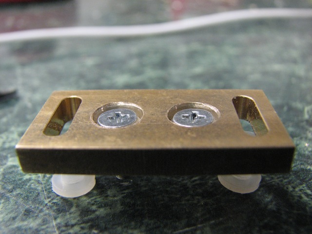
I really like Dave's diode mounting blocks, and in my new projector, I'm planning to use 'em for a 445 as well as some LOC reds that I'll be combining. This brings with it a challenge, of course. The mounts aren't isolated, and neither are the diodes. I decided that the best option would be to build in isolation between the two portions of the mount, to reduce the amount of exposed metal that's live. This also has the advantage that the isolated portion is assembled *once*. I won't have as much risk of accidentally shorting things out while tweaking the position of the mounts in the projector, since the base will be grounded anyway. The trick, of course, is actually doing it.
There are two sections that need to be isolated: the surface between the two parts of the mount, and the mounting screws between them. I decided I'd use Kapton tape between the parts, since that's what I could find easily. The screws can be made isolating in two ways: either replace them with nylon screws, or prevent the screws from directly contacting the lower part of the mount. Nylon screws have somewhat limited tensile strength, and I didn't want to calculate out the exact torque I'd need for sufficient thermal bonding. Instead, I put nylon shoulder washers between the screw and the lower mounting block. This keeps the screws electrically connected to the upper (diode) part of the block, but the insulating surface is in compression, where it's a lot stronger. There are a few modifications needed to make this all fit, though - screws and washers are a lot bigger than just screws.
The first step was to take the washers and countersink their tops, so that the original countersunk screws will fit deeply into them. I couldn't find a countersink with the right angle, but my regular drill bits seemed about right; I used a drill bit much larger than the washer and cut a conical countersink into their tops. The washers were held in place for drilling by pressing them into a close-fit hole in a wooden block. Here are 'before' and 'after' shots:
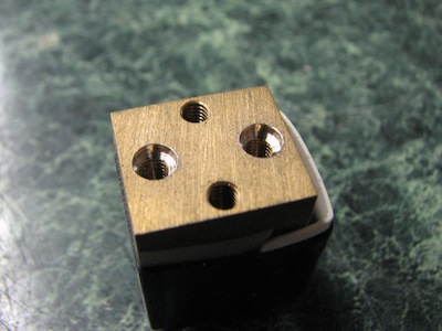
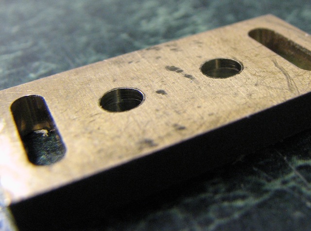
The next step is to enlarge the holes in both parts of the mounting block. The lower part should be drilled large enough for the washer to fit through it. The washer also needs to protrude a little bit into the upper block to make sure the screw stays away from the lower block. Finally, the countersink holes in the lower block had to be counterbored to a flat bottom for the washer. I used a #24 drill, followed by a 1/2" two-flute end mill. The results:
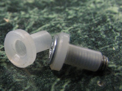
At this point, when the washers are inserted, the screw heads sit notably below the bottom surface of the lower plate - like so:
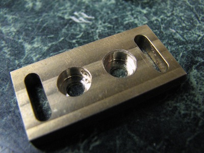
Now for some cleanup. This part is important. After drilling out the holes in the bottom plate, there will be a ragged edge sticking out from around the hole. This will short the two parts if it's not cleaned up:
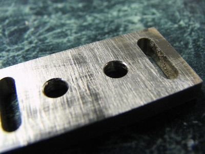
I alternated a few times between a hole deburring tool and a file over the entire surface. This was needed on both portions of the mount, not just the lower one; the upper didn't need as much, but better safe than sorry. I also filed the bottom surface of the lower block to get rid of bumps from the drilling. Eventually, the bottom was a lot cleaner:
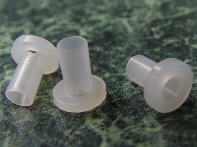
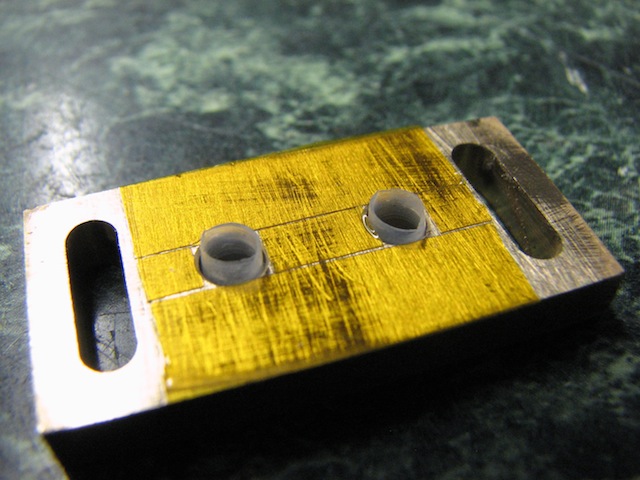
Next up, the Kapton. I had a reel of narrow tape, so I used an X-acto knife to cut strips of the right size; alternately, I could have cut holes in a larger sheet. Then I cut the ends off the washers so that they only extend a millimeter or two above the surface. Diagonal cutters worked fine for this; nylon cuts easily.
And that's about it. On my first attempt, I failed to clean up the holes on the bottom mounting block enough, and was surprised when my meter happily reported continuity between the two blocks. I did this after mounting the diodes, so you can see the protective tape I wrapped around the rest of the upper block:
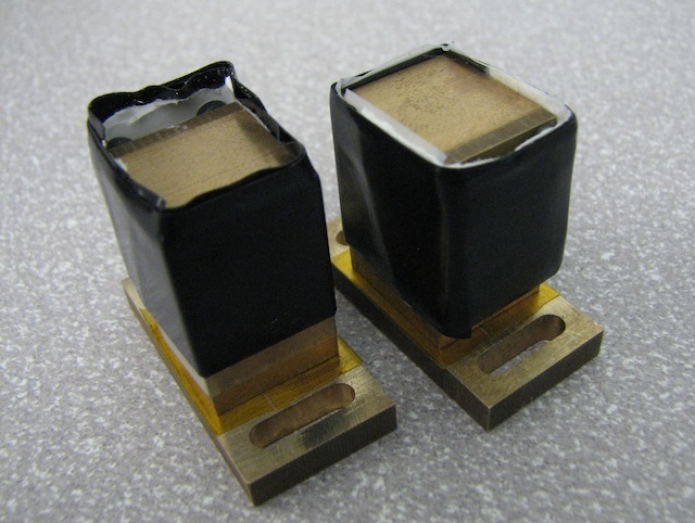
Tada!

 Reply With Quote


 This also has a much smaller footprint.
") foot print??? in my experience those who talk about footprint have enough dead space in their projector to bury a doberman in.
foot print??? in my experience those who talk about footprint have enough dead space in their projector to bury a doberman in.
 dave
dave
