Hello guys,
I'm new on the forum, and a first search didn't find any threads about this application.
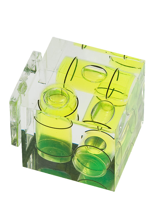
Any ideas on how to verify the alignment on a "home made" roller alignment tool, similar to this commercial product?
My concern is about being sure the laser is "exactly" perpendicular to the base.
Best regards!
Lucas

 Reply With Quote