Page 3 of 6 FirstFirst 123456 LastLast
Results 21 to 30 of 54

Thread: A sneak peek!

  1. #21
    Join Date
    May 2006
    Location
    Native Floridian
    Posts
    3,136

    Default

    Did you end up using Hobbs little bundle of joy transimpedance circuit?
    I tried that circuit but didn't have much luck with it. Currently the photodiodes are feeding jfet amps with the bootstrap and cascode removed. That is one part of the circuit I want to revisit and improve a bit.

    Dave, the 60Xs all used AR coated glass as the pickoff. With either a mylar or alumina disk as the attenuator.
    The pickoff I have now I got from dsli_jon, and is very nice, the splitter actually is kicking about 10% into the photodiode. The glass I plan on using will be closer to .5%, so current configuration would represent a system with much higher power lasers. Still plenty of playing around to do before I have anything remotely available.

    As for beta testing - you should know by now that you don't even have to ask. Just let me know when you're coming and I'll rip the covers off the projector, get some steaks out of the freezer, and fire up the grill!
    Thanks Buffo, probably going to be quite a few more weeks.

  2. #22
    Join Date
    Nov 2005
    Location
    Melbourne, Australia
    Posts
    3,702

    Default

    Nice work!
    KVANT Australian projector sales
    https://www.facebook.com/kvantaus/

    Lasershowparts- Laser Parts at great prices
    https://www.facebook.com/lasershowparts/

  3. #23
    Join Date
    Jan 2008
    Location
    Nootdorp, Zuid-Holland, Netherlands
    Posts
    162

    Default

    HE Laserscan has a built in Colour correction function, will this do the same? I have not yet played with this feature since my lasers haven't arrived yet.


    Life is short.... Ride it hard!!

  4. #24
    Join Date
    Jan 2008
    Location
    Stockholm, Sweden
    Posts
    799

    Default

    No. If I understand things correctly this is an optical feedback circuit. No software can do this.

    Very nice work DZ! Hopefully this can improve the poor modulation of my laserwave greenie.

  5. #25
    Join Date
    Jan 2008
    Location
    Nootdorp, Zuid-Holland, Netherlands
    Posts
    162

    Default

    but it would take away part of the problem right?
    Life is short.... Ride it hard!!

  6. #26
    Join Date
    Dec 2008
    Location
    Southport, UK
    Posts
    2,746

    Default

    Quote Originally Posted by Frixxion View Post
    but it would take away part of the problem right?
    No DZ's circuit is actively monitoring the output from the lasers, keeping it's output linear with the control input. Lasers unfortunately are quite unstable, for example; as you try to increase it's output in a linear fashion, it may behave to a degree but it will generally flicker high, low, or increase and decrease in steps, peaks and troughs, further; if the required output is say 50%, it may fluctuate a fair bit above and below 50% before it settles. All of this means poor colour blending/brightness gradients in the display. DZ's circuit will actively keep control of the lasers at high speed, by actually looking at the output with a photo diode, counteracting these characteristics.
    http://img62.imageshack.us/img62/3985/laser.gif

    Doc's website

    The Health and Safety Act 1971

    Recklessly interfering with Darwin’s natural selection process, thereby extending the life cycle of dim-witted ignorami; thus perpetuating and magnifying the danger to us all, by enabling them to breed and walk amongst us, our children and loved ones.


  7. #27
    Join Date
    May 2007
    Location
    Sydney, Australia
    Posts
    81

    Default

    Very nice - well done! 
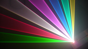
The comparison videos really show the improvement.
    B.

  8. #28
    mixedgas's Avatar
    mixedgas is offline Creaky Old Award Winning Bastard Technologist
    Infinitus Excellentia Ion Laser Dominatus
    Join Date
    May 2007
    Location
    A lab with some dripping water on the floor.
    Posts
    10,051

    Default

    Quote Originally Posted by Frixxion View Post
    but it would take away part of the problem right?
    That menu takes care of color balence and color linearity. It does not help with the lag in blue turn on time compared to the green lasers, or the lead in turn on time in the red lasers, compared to the green lasers.

    Light feedback, plus some creative work with a derivative circuit, will greatly improve the blue situation.


    Steve
    Qui habet Christos, habet Vitam!
    I should have rented the space under my name for advertising.
    When I still could have...

  9. #29
    Join Date
    Dec 2006
    Location
    Netherlands
    Posts
    983

    Default

    Quote Originally Posted by mixedgas View Post

    Light feedback, plus some creative work with a derivative circuit, will greatly improve the blue situation.
    Sorry to be skeptic, but I highly doubt it. The reason is that the blue laser has slow dynamics. An optical feedback circuit closed around the slow internal dynamics will not speed it up. In fact it could make the output unstable as you will probably try to increase the outerloop gain.

    Think of it as trying to control a sluggish Boeing 747 with an F16 autopilot. The autopilot will not make the 747 any more agile.

    What DZ is doing is slowing down the faster lasers, flying an f16 like a sluggish 747, which will work. Since the the environment of the lasers are well controlled (temp mainly) there are no significant outside disturbances so an extra feedback loop is not needed. Feedback is used in control to take care of outside disturbances. If those are not significant and you are controlling a predictable system (like our lasers) feedforward is the way to go.

    To be complete: the laser's internal feedback control (current, temperature) make it a predictable system so is can be regarded as a 'black box' with a known mapping from modulation input to light output.

  10. #30
    Join Date
    Jul 2007
    Location
    Knoxville, TN, USA
    Posts
    3,154

    Default

    OK, so a couple of questions from someone who still has the big "?" over their head ():

    1. In "less-electronically-oriented" layman's terms, what is the end-result functional difference between this particular circuit, and the color correction board?

    2. Would this be applicable in a "less common" projector setup, such as RGBV?
    RR

    Metrologic HeNe 3.3mw Modulated laser, 2 Radio Shack motors, and a broken mirror.
    1979.
    Sweet.....

Posting Permissions

  • You may not post new threads
  • You may not post replies
  • You may not post attachments
  • You may not edit your posts
  •